seat Workshop Repair Guides

SEAT Workshop Service and Repair Manuals

Ignition system, glow plug system > < Diesel direct injection system: repair
Motor for plate in inlet manifold: check
Special tools and workshop equipment required
t  Fault reader -V.A.G 1551- or vehicle system checker -V.A.G 1552- with cable -V.A.G 1551/3B-
t  Checking box -V.A.G 1598/22-
t  Manual multimeter -V.A.G 1526 A- or multimeter -V.A.G 1715-
t  Auxiliary measuring set -V.A.G 1594 C-
t  Current circuit diagrams
Checking process
–  Connect the -V.A.G 1551- (-V.A.G 1552-), and using the corresponding “direction code” 01, select the control unit for engine electronics. When doing this, the engine must be idling: (Fault reader: Turn on and select the control unit for engine electronics → Chapter).
   
Indication on the display:
–  Press the keys 0 and 3 for the function “Actuator diagnosis”.
 
Fast data transmission              HELP
Select the function XX                  
Indication on the display:
–  Confirm the entry with Q.
–  Press until the following message appears.
 
Fast data transmission                 Q
03 -Actuator diagnosis                  
Indication on the display:
When the motor for the inlet manifold plate is activated, the sound of the combustion changes (the servomotor opens and closes the inlet manifold plate).
If no change is noted in the sound of the combustion:
–  Contiue diagnosing the actuators to the end.
–  Press the keys 0 and 6 for the function “End data transmission” and confirm with Q.
–  Turn off the ignition.
 
Actuator element diagnosis            ->
Motor for inlet manifold plate V157     
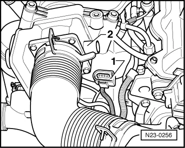
–  Remove the connector -1- from the motor for the inlet manifold plate -2-.
–  Turn on the ignition.
  N23-0256
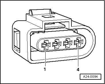
–  Measure the supply voltage of the motor for the inlet manifold plate on contact 4 of the connector and engine ground, and then on contacts 4 and 1 of the connector.
   Theoretical value: approx. voltage of the battery
If the theoretical value is not reached:
–  Turn off the ignition.
  A24-0094
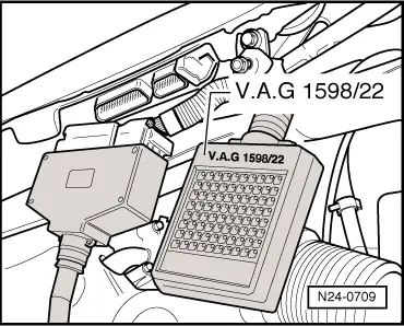
–  Connect the -V.A.G 1598/22- checking box to the cable harness of the control unit.
–  Check for breakage in the cables between the checking box and the connector, following the current circuit diagrams.
   Contact 2+female 3
   Contact 3+female 49
   Cable resistance: 1,5Ω max.
–  Additionally, check the cables for short circuiting between them, to ground and to battery positive.
   Theoretical value: ∞ Ω
If no fault is found in the cables:
–  Replace the engine control unit -J248- → Chapter.
  N24-0709

Ignition system, glow plug system > < Diesel direct injection system: repair