skoda Workshop Repair Guides

Skoda Workshop Service and Repair Manuals

Setting output shaft > < Control measurement
Disassembling and assembling the output shaft
Special tools and workshop equipment required
t  Thrust washer -MP 3-407-
t  Thrust piece -MP 3-408-
t  Pressure plate - MP 3-411-
t  Thrust piece -MP 3-423-
t  Thrust piece -MP 3-448-
t  Thrust piece -MP 3-449-
t  Pipe section -MP 3-450-
t  Thrust ring -MP 3-452-
t  Thrust washer -MP 3-455-
t  Alignment rails -MP 3-457-
t  Thrust washer -MP 3-460-
t  Pipe section -MP 3-461-
t  Insertion tool - MP 3-466-
t  Tapered-roller bearing extractor -V.A.G 1582-
t  Gripper -V.A.G 1582/5-
t  Two-arm extractor, e.g. -Kukko 20/10-
t  Hook, e.g. -Kukko 1-250-
t  Interior extractor, e.g. -Kukko 21/6-
t  Countersupport, e.g. -Kukko 22/2 -
t  Separating device, e.g. -Kukko 17/2-
  Note
t  When installing new pinions or a new output shaft observe the technical data → Chapter
t  Removing and installing output shaft → Chapter
t  Replace both tapered-roller bearings together.
t  The gearboxes manufactured as of 09.00 have a modified 1st gear synchronisation.
   
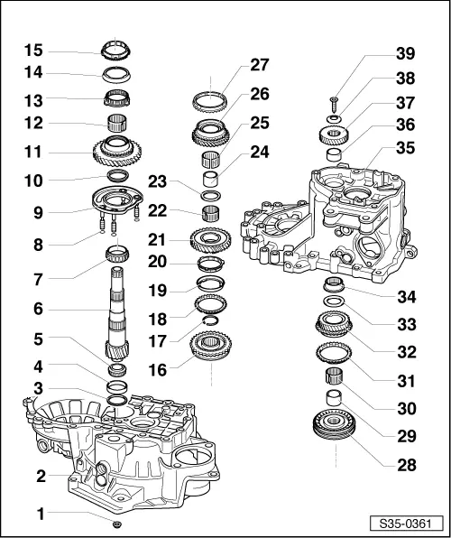
1 - Nut, 25 Nm + 90°
q   4 nuts for bearing support
2 - Clutch housing
3 - Adjusting washer
q   Determining thickness - Setting output shaft → Chapter
4 - Outer ring/tapered-roller bearing small
q   removing → Fig.
q   installing → Fig.
5 - Inner ring/tapered-roller bearing small
q   remove → Fig.
q   installing → Fig.
6 - Output shaft
q   is paired with the gear pinion of the final drive, replace together
q   adjust → Chapter
7 - Inner ring/tapered-roller bearing large
q   remove → Fig.
q   inserting → Fig.
8 - Gasket ring
q   Insert gasket rings (4 pieces) on the bearing support screws
9 - Bearing support
q   with outer ring/tapered-roller bearing large and with screws
q   Always replace outer ring together with tapered-roller bearing large and bearing support
10 - Thrust washer
q   Heel of thrust washer points to tapered-roller bearing
11 - 1st gear sliding gear
12 - Needle bearing
q   for 1st gear
13 - Inner synchronizer ring for 1st gear
q   check for wear → Fig.
q   check lands for wear
q   Fitting position → Fig.
14 - Outer ring for 1st gear
q   place onto the inner ring Pos. 13, fitting position → Fig.
q   replace if damaged or worn
15 - 1st gear synchronizer ring
q   Identification → Fig.
q   check for wear → Fig.
q   Fitting position → Fig.
16 - Sliding sleeve with 1st and 2nd gear synchronizer body
q   after removing the circlip Pos. 17 pull off above bearing support → Fig.
q   disassembling → Fig.
q   Assembling the sliding sleeve with synchronizer body → Fig. and → Fig.
q   Fitting position → Fig.
q   pressing on → Fig.
17 - Circlip
18 - 2nd gear synchronizer ring
q   Identification → Fig.
q   check for wear → Fig.
q   insert in such a way that the recesses lock into the arresters on the sliding sleeve Pos. 16
19 - Outer ring for 2nd gear
q   insert into synchronizer ring Pos. 18, fitting position → Fig.
q   replace if damaged or worn
20 - Inner synchronizer ring for 2nd gear
q   check for wear → Fig.
q   check lands for wear
q   Fitting position → Fig.
21 - 2nd gear sliding gear
q   Fitting position → Fig.
22 - Needle bearing
q   for 2nd gear
23 - Thrust washer
24 - Bushing for 3rd gear needle bearing
q   press off with 2nd gear sliding gear → Fig.
q   pressing on → Fig.
25 - Needle bearing
q   for 3rd gear
26 - 3rd gear sliding gear
27 - 3rd gear synchronizer ring
q   check for wear → Fig.
28 - Sliding sleeve with 3rd and 4th gear synchronizer body
q   press off → Fig. together with 2nd sliding gear Pos. 21 and 3rd gear Pos. 26
q   disassembling → Fig.
q   Fitting position sliding sleeve with synchronizer body → Fig.
q   Assembling the sliding sleeve with synchronizer body → Fig. and → Fig.
q   pressing on → Fig.
29 - Bushing
q   for needle bearing
q   press off with sliding sleeve and 3rd and 4th gear synchronizer body Pos. 28 → Fig.
q   pressing on → Fig.
30 - Needle bearing
q   for 4th gear
31 - 4th gear synchronizer ring
q   check for wear → Fig.
32 - 4th gear sliding gear
33 - Thrust washer
34 - Needle bearing
q   for output shaft
q   extracting → Fig.
35 - Gearbox housing
36 - Bushing
q   for needle bearing of output shaft
q   pressing off → Fig.
q   pressing on → Fig.
37 - 5th gear sliding gear
q   removing and installing → Chapter
38 - Disc spring
q   Fitting position → Chapter
39 - 80 Nm
q   holds disc spring in position with sleeve socket on screw head → Chapter
q   always replace → Electronic Catalogue of Original Parts

   
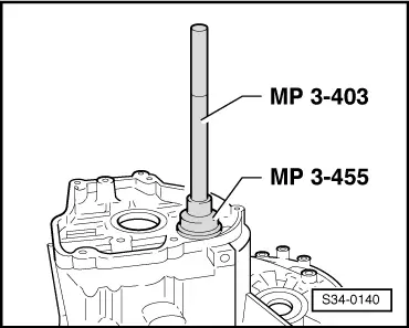
Driving out needle bearing
  S34-0140
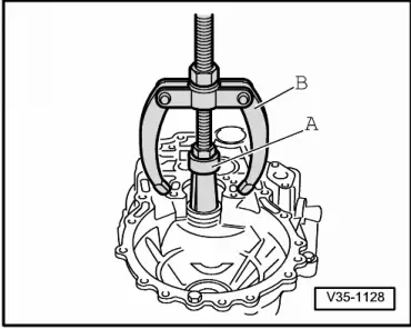
Removing outer ring/tapered-roller bearing small
A - Interior extractor 37 ... 46 mm, e.g. -Kukko 21/6-
B - Countersupport, e.g. -Kukko 22/2-
  V35-1128
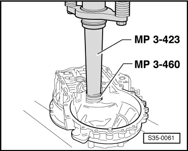
Pressing in small outer ring/tapered-roller bearing
  S35-0061
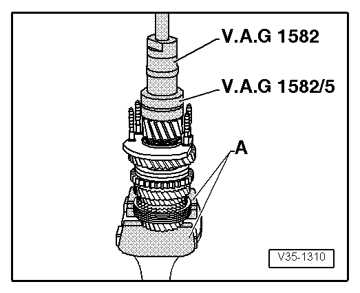
Extracting small inner ring/tapered-roller bearing
A - Vice-Protective jaws
–  Position hook on bearing rollers and pull off inner ring.
  V35-1310
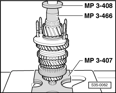
Press in small inner ring/tapered-roller bearing
  S35-0062
Pressing off synchronizer body, sliding sleeve, 2nd, 3rd and 4th gear with needle bushing
A - Separating device 22 ...115 mm e.g. -Kukko 17/2-
B - Screw M10 x 20
–  Position separating device under 2nd gear Pos. 21 sliding gear and pull off.
  Note
Support the separating device in such a way that the 1st and 2nd gear sliding sleeve is not drawn off.
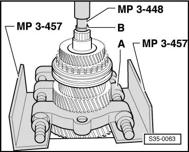
  s35-0063
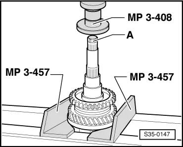
Remove sliding sleeve with synchronizer body via bearing support
A - Screw M10 x 20
–  Remove circlip Pos. 17.
–  Remove together with 1st gear sliding gear and sliding sleeve with 1st and 2nd gear synchronizer body.
  S35-0147
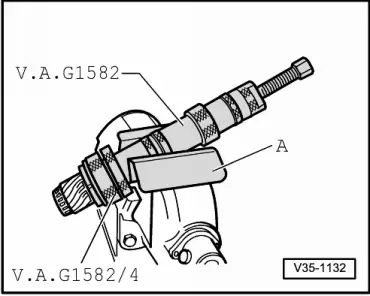
Pulling off large inner ring/tapered-roller bearing
A - Protective jaws
–  Before fitting the extractor screw the screw M10 x 20 into the output shaft bore.
  V35-1132
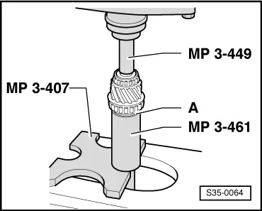
Pressing on large inner ring/tapered-roller bearing
A - Thrust washer
–  Insert thrust washer before pressing in the inner ring. The collar is located on the side of the inner ring.
  S35-0064
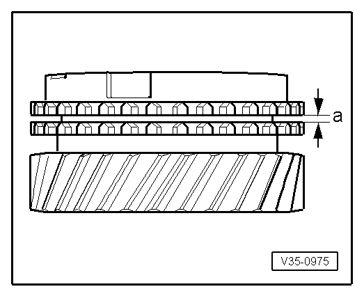
Check 3rd and 4th gear snychronizer ring for wear
–  Press the synchronizer ring on the cone of the sliding gear and measure clearance -a- with a feeler gauge.
  V35-0975
 Fitting dimensionWear limit
Dimension -a-1.0 ... 1.7 mm0.5 mm

   
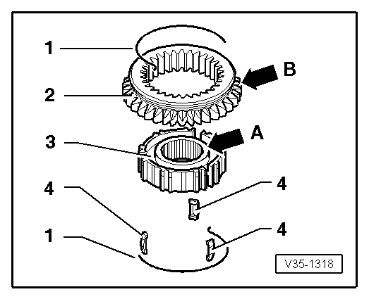
Disassembling and assembling the sliding sleeve and 1st and 2nd gear synchronizer body
1 - Spring
2 - Sliding sleeve
3 - Synchronizer body
4 - Arresters for synchronizer body
–  Slide the sliding sleeve over the synchronizer body.
The chamfers ( → Fig.) and the outer serration of the sliding sleeve -arrow B- point in one direction after assembly. The recesses for the arresters on the synchronizer body and the sliding sleeve must be positioned opposite.
  V35-1318
Assembling the sliding sleeve and 1st and 2nd gear synchronizer body
l  The sliding sleeve is drawn over the synchronizer body.
–  Insert arresters and mount springs with 120° offset. The angled ends of the springs must grip into the opening in the arrester for the synchronizer body.
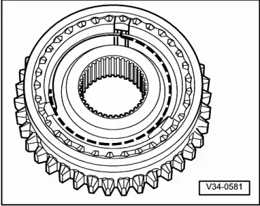
  V34-0581
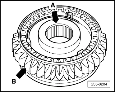
Fitting position of the sliding sleeve and 1st and 2nd gear synchronizer body
The chamfers -arrow A- and the outer serration of the sliding sleeve -arrow B- point to 2nd gear sliding gear .
  S35-0204
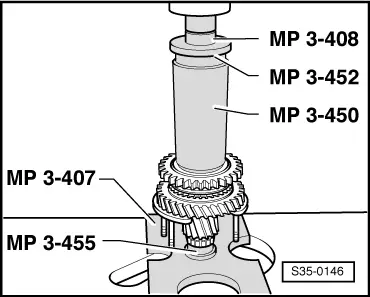
Press on the sliding sleeve and 1st and 2nd gear synchronizer body
  Note
Before pressing on position the synchronizer ring for the 1st gear on the 1st gear sliding gear.
  S35-0146
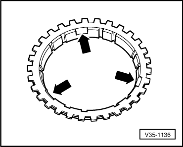
Difference between the 1st and 2nd gear synchronizer rings
t  1st and 2nd gear synchronizer rings are identical; identification → Fig.
  V35-1136
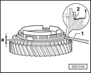
Check 1st and 2nd gear inner ring for wear
–  Press the inner ring on the cone of the sliding gear and measure clearance -a- with a feeler gauge.
  S35-0154
 Fitting dimensionWear limit
Dimension -a-0.75 ... 1.25 mm0.3 mm

   
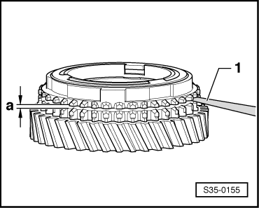
Check 1st and 2nd gear snychronizer rings for wear
–  Press the synchronizer ring (outer and inner) on the cone of the sliding gear and measure clearance -a- with a feeler gauge.
  S35-0155
 Fitting dimensionWear limit
Dimension -a-1.2 ... 1.8 mm0.5 mm

   
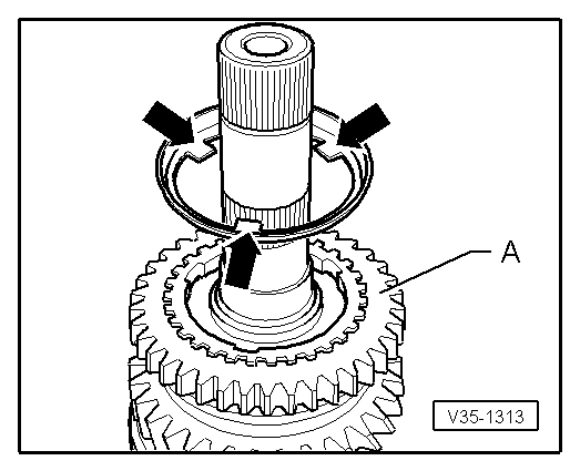
Fitting position of the 2nd gear outer ring
The pegs -arrows- point towards the 1st gear sliding gear -A-.
  V35-1313
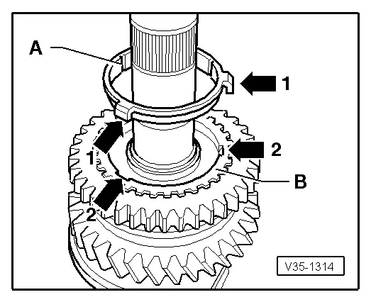
Fitting location inner ring -A-
The pegs -arrow 1- lock into the recesses -arrow 2- of the synchronizer ring -B-.
  V35-1314
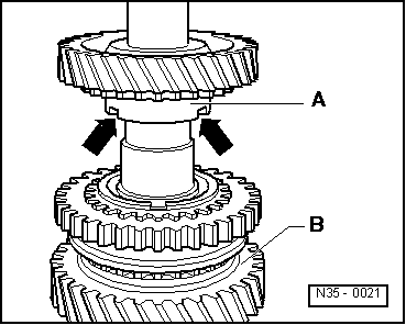
Fitting position of the 2nd gear pinion
The higher collar -A- points towards the 1st gear -B-. The recesses in the collar -arrows- lock into the pegs of the outer ring → Fig..
  N35-0021
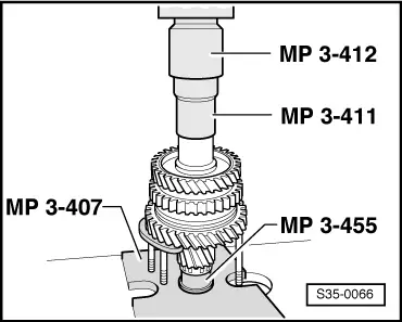
Insert thrust washer and press on needle bushing for 3rd gear.
–  Insert needle bearing, sliding gear and 3rd gear synchronizer ring.
  S35-0066
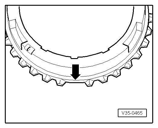
Identification 3rd gear synchronizer ring
Identification: every 3 x 1 tooth missing -arrows-.
  V35-0465
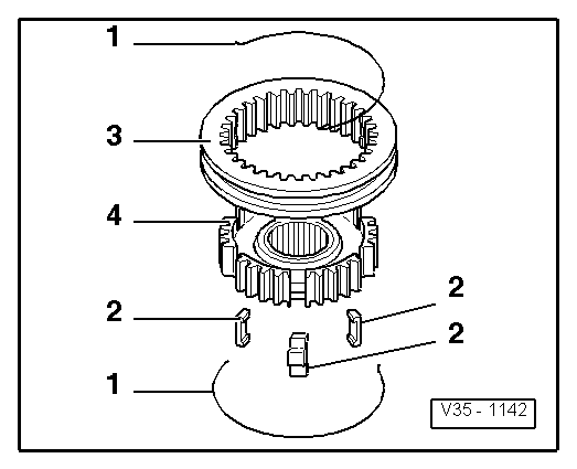
Disassembling and assembling the sliding sleeve and 3rd and 4th gear synchronizer body
1 - Spring
4 - Arresters for synchronizer body
3 - Sliding sleeve
4 - Synchronizer body
–  Slide the sliding sleeve over the synchronizer body.
The recesses for the arresters on the synchronizer body and the sliding sleeve must be positioned opposite.
  V35-1142
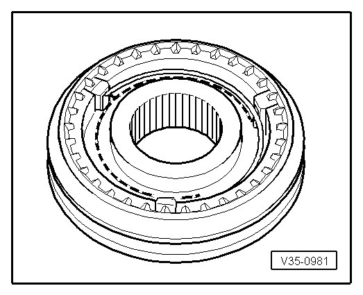
Assembling the sliding sleeve and 3rd and 4th gear synchronizer body
The sliding sleeve is drawn over the synchronizer body.
–  Insert arresters and mount springs with 120° offset. The angled ends of the springs must grip into the opening in the arrester for the synchronizer body.
  V35-0981
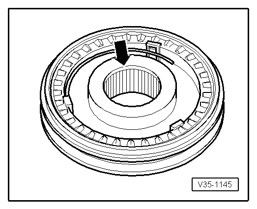
Fitting position of the sliding sleeve and 3rd and 4th gear synchronizer body
The chamfers -arrow- point towards the 4th gear.
  V35-1145
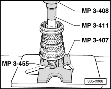
Press on the synchronizer body and the 3rd and 4th gear sliding sleeve
  S35-0068
Pressing on bushing for 4th gear needle bearing
–  Insert needle bearing, 4th gear sliding gear and synchronizer ring.
–  Position the thrust washer on the 4th gear sliding gear.
  S35-0068
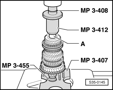
Pressing on bushing for needle bearing/output shaft -A-
  S35-0145
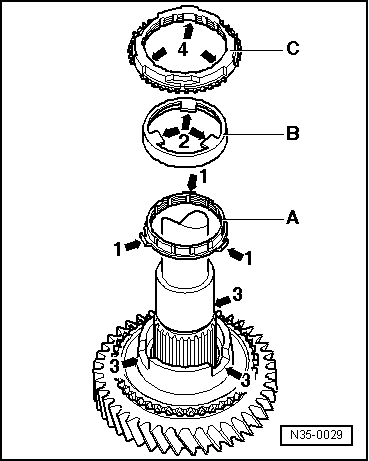
Fitting position of the outer ring, inner ring and 1st gear synchronizer ring
–  Position the inner ring -A- on the 1st gear sliding gear.
The angled lands -arrow 1- point towards the outer ring -B-.
–  Position the outer ring -B-.
Lock the lands -arrows 2- in the recesses of the sliding gear -arrows 3- .
–  Position the synchronizer ring -C-.
Lock the recesses -arrows 4- in the lands -arrows 1- of the inner ring -A-.
  N35-0029
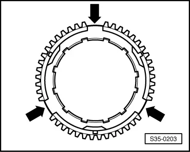
Identification of the 1st and 2nd gear synchronizer ring
Identification: every 3 x 2 teeth missing -arrows-
  S35-0203

Setting output shaft > < Control measurement