
Fabia Mk1
| Piston and conrod - Summary of components |
 Note
Note| t | The following conrod versions are fitted: |
| t | Conrods with fit pin Pos.6, use here conrod bolts without centering. |
| t | Conrods without fit pin, use here conrod bolts with centering. |

| 1 - | Piston rings |
| q | Offset joint 120° |
| q | use piston ring pliers for removing and installing |
| q | Marking „TOP“ faces up |
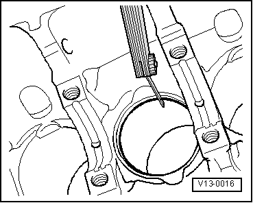
| q | Inspect gap clearance → Fig. |
| q | Inspect end clearance → Fig. |
| 2 - | Piston |
| q | with combustion chamber |
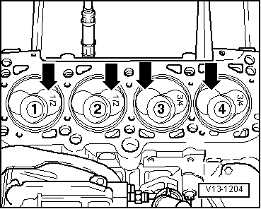
| q | mark installation position and matching cylinder |
| q | Installation position and assignment of piston and cylinder → Fig. |
| q | arrow on piston crown faces towards the belt pulley side |
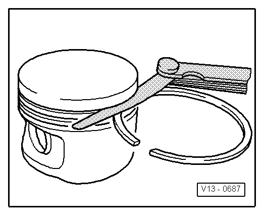
| q | use piston ring tensioning strap for installing |
| q | replace piston if there is any sign of crack formation on the piston body |
| q | inspect piston projection at TDC → Chapter |
| q | Ø Piston: 79.47 mm |
| 3 - | Piston pin |
| q | if stiff, heat piston to 60°C |
| q | use drift -VW 222 A- for removing and installing |
| 4 - | Circlip |
| 5 - | Conrod |
| q | pay attention to different version |
| q | replace as a set only |
| q | mark assignment to cylinder, refer to -A- |
| q | Fitting location: Markings -B- must be positioned one above the other and point to the belt pulley side |
| q | axial clearance |
| Wear limit: 0.37 mm |
| 6 - | Fit pin |
| q | the fit pins must fit tightly in the conrod, not in the cap |
| 7 - | Bearing shell |
| q | Check fitting position |
| q | do not mix up used bearing shells (mark) |
| q | ensure tightly located in retaining lugs |
| 8 - | Cylinder block |
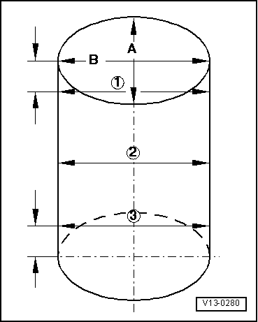
| q | inspect cylinder bore → Fig. |
| q | Ø Cylinder: 79.51 mm |
| 9 - | Conrod bearing cap |
| q | Check fitting position |
| 10 - | Oil injection nozzle |
| q | for piston cooling |
| 11 - | 25 Nm |
| q | replace without sealant |
| 12 - | Conrod bolt, 30 Nm + torque a further + 90° (1/4 turn) |
| q | replace |
| q | Oil thread and contact surface |
| Piston ring | New (mm) | Wear limit (mm) |
| 1. Compression ring | 0.20 to 0.40 | 1,0 |
| 2. Compression ring | 0.20 to 0.40 | 1,0 |
| Oil scraper ring | 0.25 to 0.50 | 1,0 |
|
|
| Piston ring | New (mm) | Wear limit (mm) |
| 1. Compression ring | 0.06 to 0.09 | 0,25 |
| 2. Compression ring | 0.05 to 0.08 | 0,25 |
| Oil scraper ring | 0.03 to 0.06 | 0,15 |
Note
|
|
Note
|
|