skoda Workshop Repair Guides

Skoda Workshop Service and Repair Manuals

Installing the gearbox > < Removing and installing gearbox (Fabia II, Roomster)
Removing the gearbox
–  Shift selector lever into position „P“.
  Note
Do not take out ignition key.
–  If present, remove engine cover → Engine; Rep. gr.10.
   
–  Remove battery → Electrical System; Rep. gr.27.
–  Remove air filter box completely with air guide hose → Engine; Rep. gr.24.
  N34-11366
–  Remove battery tray, to do so release the screw and the nuts -arrows-.
  N37-10427
–  Lever off the selector lever control cable -A- from the gearshift lever with the removal tool for the inner lining of the door panel-MP8-602/1-.
  S34-1142
–  Detach the lock washer -arrow- of the selector lever control cable.
–  Then carefully push the selector lever control cable to the rear, remove it from the cable support and tie up.
  Note
t  The lock washer -arrow- of the selector lever control cable must always be replaced → Electronic Catalogue of Original Parts.
t  Do not bend or buckle selector lever control cable.
–  Removing starter → Electrical System; Rep. gr.27.
When removing, it is recommended to begin with the bottom starter screw.
–  Release all the upper gearbox connecting screws to the engine. To this end, use if necessary socket insert -T10035- or socket insert -T10061-.
  N34-11373
One of the screws is located in the opening for the starter -arrow-.
–  Screw out this screw.
  Caution
Under no circumstances must the plug contacts in the plug of the gearbox be touched with the hands, because the control unit can be destroyed through static discharge as well as the mechatronics.
–  Grab with the hand (without gloves) at the mass, in order to discharge yourself electrostatically.
  N34-11409
–  Unlock the cap of the plug on the mechatronics by pulling in -direction of arrow- and disconnect the plug.
–  Unclip the electrical cables from the top bracket at the front of the gearbox.
For vehicles 1.2/77 kW
  N34-11386
–  Open the bracket -A- for the coolant hoses and unclip the coolant hoses. Do not open the coolant lines.
–  Then unlatch the bracket in the lower area -arrow 1- and detach it upwards from the timing case cover -B--direction of arrow-.
Continued for all vehicles
–  Remove front wheels → Chassis; Rep. gr.44 and raise the vehicle.
–  Remove the sound dampening system → Body Work; Rep. gr.50.
–  Remove the front left wheelhouse liner → Body Work; Rep. gr.66.
  S34-1268
–  Unplug connector -arrow-.
  N19-10398
–  Release the fan shroud on the catch hook e.g. using a screwdriver and remove → Engine; Rep. gr.19.
For vehicles 1.2/77 kW
  N19-10333
–  Remove lambda probe -G39--1-.
–  Disconnect the plug -2- from the alternator and remove the heat shield -3- from the exhaust gas turbocharger -arrows-.
Continued for all vehicles
  S34-1267
–  Unhook the plug connections -1 … 3- from the bottom bracket at the front of the gearbox and disconnect.
–  Remove pre-exhaust pipe with catalytic converter -4- → Engine; Rep. gr.26.
  S34-1270
Vehicles with radiator fan control unit -J293-
–  Unscrew the nuts -3- from the left frame side rail and tie up the radiator fan control unit -J293--4-.
  Note
Do not disconnect the plugs -1- and -2-.
Vehicles with power steering
  S48-0305
–  Open the spacer holder -1- and remove the cables -2- and -3- for the power-assisted steering gear.
–  Remove the engine pump aggregate for the power-assisted steering with the bracket from the frame side rail and tie up to the side → Chassis; Rep. gr.48.
Continued for all vehicles
  S48-0141
–  Remove pendulum support from gearbox, to do so release screws -1- and -2-.
  S48-0112
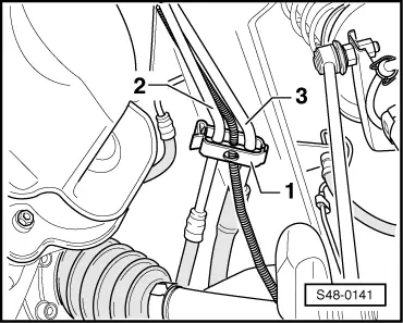
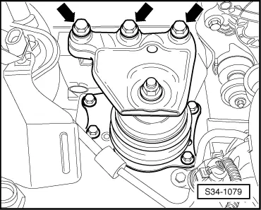
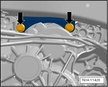
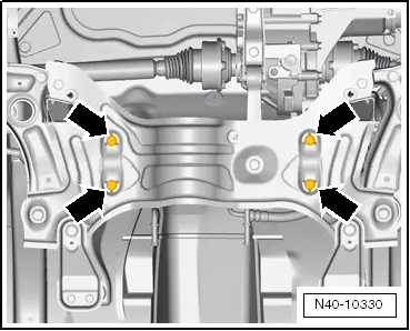
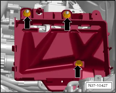
–  Release the screws -arrows- for the steering gear on the assembly carrier and tie up the steering gear in the right area, e.g. on the bracket for the ABS control unit.
–  Fix the assembly carrier before removing → Chassis; Rep. gr.40.
–  Remove assembly carrier without steering gear → Chassis; Rep. gr.40.
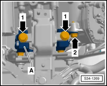
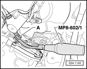
–  Unscrew both drive shafts from the gearbox.
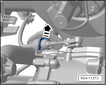
–  Tie up right drive shaft as far as possible, e.g. with cord. Avoid damaging the paintwork on the drive shaft during this operation.
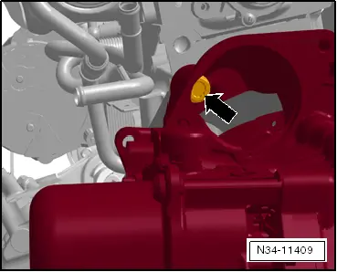
–  Swivel the left drive shaft into the wheelhouse and secure it to the suspension strut, e.g. with cord. Avoid damaging the paintwork on the drive shaft during this operation.
  N40-10330
–  Removing the right flange shaft.
–  If hose and cable connections are located in the area of the lifting eye of the engine for the supporting device -MP9-200 (10-222A)-, these must now be removed.
  N34-11389
–  Install supporting device -MP9-200 (10-222A)-. For this purpose, position the supports -A- next to the screw -arrow 1- and the support of the front flap -arrow 2- as shown.
–  Slightly pre-tension the engine/gearbox unit via the spindles, do not raise.
  S34-1266
–  Release screws -arrows- for engine mounting from engine holder.
  Note
Do not slacken the fixing nut for the engine mount.
  S34-1079
–  Unscrew the fixing screws -arrows 1- for the gearbox mount at the console -A-.
–  Screw out the rear fixing screw -arrow 2- for the console -A- at the gearbox.
  S34-1269
–  Lower the engine/gearbox assembly via the spindles to the dimension -a- by approx. 85 mm.
–  In addition, slightly lower the engine.
  N34-11348
–  Screw out the remaining fixing screws -arrows- of the console at the gearbox, starting from the left wheelhouse.
–  Remove console from gearbox.
  N34-11426
For the removal of the gearbox 0AM the gearbox mount -3282- is aligned with the adjusting plate -3282/59- and placed on the engine/gearbox jack -V.A.G 1383 A-.
–  Align arms of the gearbox mount to match the holes in the adjusting plate -3282/59-.
–  Screw in the mounting elements as shown on adjusting plate -3282/59-.
–  Position the engine/gearbox jack -V.A.G 1383 A- below the vehicle.
l  The arrow symbol on the adjusting plate -3282/59- points in the direction of travel.
–  Align the gearbox mount -3282- parallel to the gearbox.
–  Screw the bolt -3282/29- into the gearbox.
–  Place both remaining mounting elements on the gearbox as shown. To do so, place the panel of the drift under the gearbox housing but not under the mechatronics.
–  Secure the gearbox with the tensioning strap -T10038-.
–  Position the gearbox by lifting the engine/gearbox jack -V.A.G 1383 A- from the bottom.
  A34-10310
–  Remove the remaining connecting screws -4…8- engine to gearbox.
  Note
The 2 bottom screws -6- and -7- secure the cover plate for the flywheel to the gearbox. Thereby, mark the fitting position of the plate for reinstalling (on vehicles 1.2/77 kW).
–  Press the gearbox off the engine and carefully swivel towards the left frame side rail.
  Note
t  The distance between the engine flange and the gearbox flange must be approx. 50 mm before lowering the gearbox.
t  Observe all lines and coolant hoses when lowering the gearbox.
–  Carefully lower the gearbox.
  S34-1178
If necessary, remove the bracket at the front of the gearbox.
  Note
If a »new« gearbox must be installed, the brackets must be fitted to the »new« gearbox.
–  Install the right flange shaft again → Chapter.
Tightening torque - 30 Nm.
Transporting the gearbox and secure to the assembly support → Chapter.
Installing the gearbox → Chapter.
  N34-11393

Installing the gearbox > < Removing and installing gearbox (Fabia II, Roomster)