| Disassembling and assembling differential gear |
| Special tools and workshop equipment required |
| t
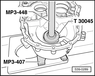
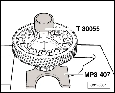
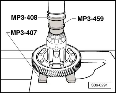
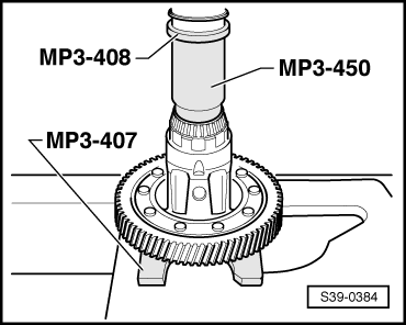
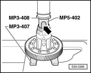
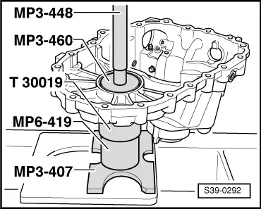
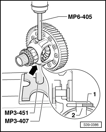
| Pressure plate -MP3-407 (VW 402)- |
| t
| Pressure spindle -MP3-408 (VW 412)- |
| t
| Pressure spindle -MP3-448 (VW 408A)- |
| t
| Pipe section -MP3-450 (VW 415A)- |
| t
| Pipe section -MP3-451 (VW 422)- |
| t
| Thrust piece -MP3-459 (VW 473)- |
| t
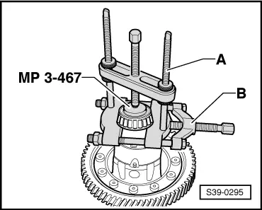
| Pressure washer -MP3-467 (40-105)- |
| t
| Assembly device -MP5-402 (3301)- |
| t
| Pressure spindle -MP6-405 (VW 411)- |
| t
| Thrust plate -T30045 (3005)- |
| t
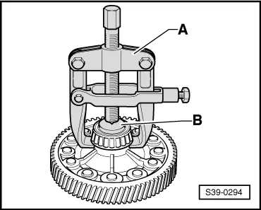
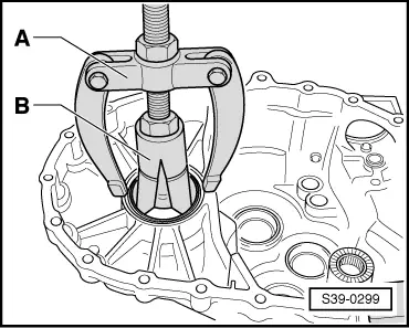
| Separating device 12...75 mm, e.g. - Kukko 17/1- |
| t
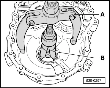
| Extractor, e.g. -Kukko 18/1- |
| t
| Interior extractor 46 up to 58 mm, e.g. -Kukko 21/7- |
| t
| Countersupport e.g. -Kukko 22/2- |
| t
| Extractor, e.g. -Kukko 204/2- |
|
|
|

 Note
Note