
Octavia Mk2
|
|
|
|
 Note
Note
|
|
Note
|
|
|
|
|
|
|
|
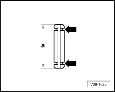
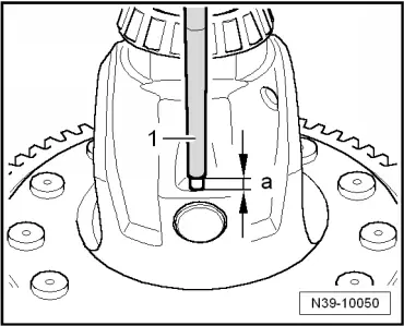
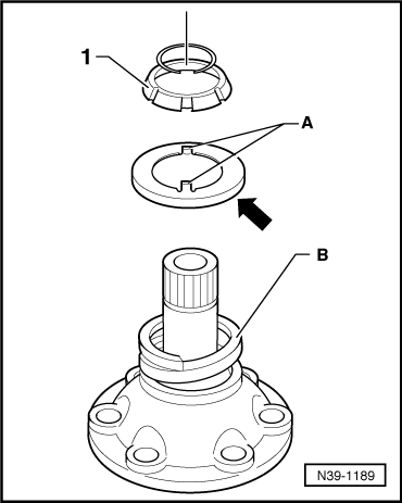
| Dimension „a“ mm | Distinguishing feature | |
| 28.5 (short tensioning sleeve) | with round slot -arrows- | |
| removing and installing → Fig. | ||
| 36.0 (long tensioning sleeve) | without round slot | |
| removing → Fig. | ||
| installing → Fig. | ||
|
|
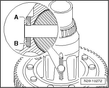
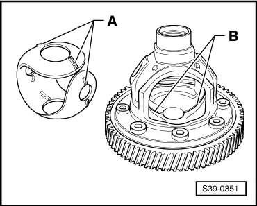
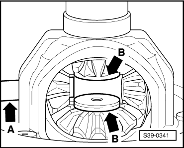
| Bore | Length of tensioning sleeve (mm) | |
| »A« | 28.5 (short tensioning sleeve) | |
| »A« and »B« | 36.0 (long tensioning sleeve) | |
|
|
|
|
|
|
|
|
|
|
|
|