skoda Workshop Repair Guides

Skoda Workshop Service and Repair Manuals

Install the double clutch "new design" as of 06.11 > < Adjust the position of the engaging bearings for clutch "K 1 and K 2" - "new design" as of 06.11
Install the double clutch - „old design“ up to 05.11
Special tools and workshop equipment required
t  Extractor -T10373-
t  Supporting bridge -T10323-
t  Thrust piece -T10368-
t  Thrust piece -T10376-
t  Adhesive -AMV 195 KD1 01-
  Note
The adjusting washer for the clutch „K1“ is installed on the large bearing, the adjusting washer for the clutch „K2“ is installed under the small bearing.
Before installing the clutch, the position of the engaging bearings „K 1 and K 2“ must be adjusted → Chapter.
The position of the engaging lever must be adjusted if:
t  The clutch was replaced
t  The engaging levers were replaced
t  The engaging bearing was replaced.
   
t  the support is also part of the control.
If all the mentioned parts are only removed and reinstalled, there is nothing to adjust.
Do not oil or grease!
  N30-10259
–  Insert the plastic support of the engaging levers and check for correct fit.
  N30-10246
–  Install small engaging lever with clamp.
The sleeve with its retaining bracket fits only in one position.
  N30-10260
Only some »older« gearboxes have no clamp. »New« gearboxes always have a clamp.
–  Check the correct fit of the engaging lever.
–  Screw down the engaging lever with 2 new screws.
Tightening torque: 8 Nm + torque a further 90° (1/4 turn)
  Note
The support of the engaging levers and the complete mechanism for the engaging bearings must be dry and free of oil or grease. If necessary, clean these component parts with a cloth.
  N30-10247
–  Insert the second »larger« engaging lever.
This »larger« lever is for the clutch „K 1“.
–  Check the correct fit of both engaging levers.
  Caution
Before performing any further assembly, check whether the clutch must be adjusted.
Further assembly can only be performed once the clutch has been adjusted!
Adjust the positions of the engaging bearings → Chapter.
  N30-10264
–  Insert the small engaging bearing -A- with the measured adjusting washer -B-.
The adjusting washer -B- belongs under the small engaging bearing -A-. Therefore, insert the adjusting washer first.
  S30-0221
The small engaging bearing fits in only one position due to the 4 grooves.
If the clutch was replaced, the adjusting washer also belongs under the bearing.
  N30-10232
–  While »turning« the bearing, check if it is correctly installed and the grooves are correctly positioned.
  N30-10265
–  Fix the adjusting washer -A- with 3 drops of glue -AMV 195 KD1 01--arrows-.
This prevents that the washer slips out of its position when the clutch is inserted.
The large adjusting washer is used for the clutch „K 1“, the small one is used for the clutch „K 2“.
–  Turn back the spindle of the extractor -T10373-.
  S30-0222
–  Insert the clutch.
–  Insert the clutch into the gearbox using the extractor -T10373-.
–  »Turn back« the spindle beforehand.
  Note
The clutch is self-adjusting. Vibrations can have a negative effect on the adjusting device. Therefore do not let the clutch fall. Do not let the clutch fall into the gearbox when installing it.
  N30-10241
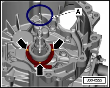
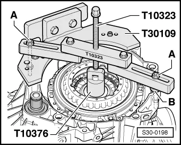
–  Position the supporting bridge -T10323- parallel to the flange of the clutch housing.
–  Equalise distances, e.g using washers -B- with a total thickness of 15 mm.
–  Attach the supporting bridge -T10323- with screws -A-.
  Note
Fasten screws -A- with nuts.
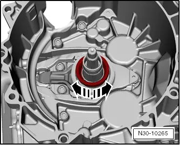
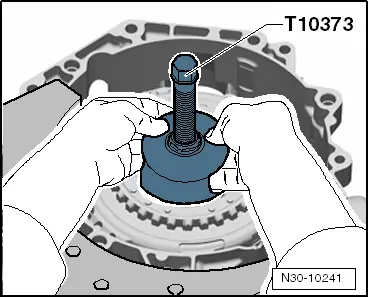
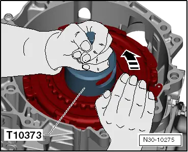
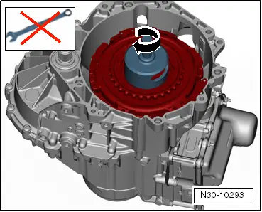
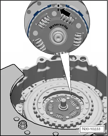
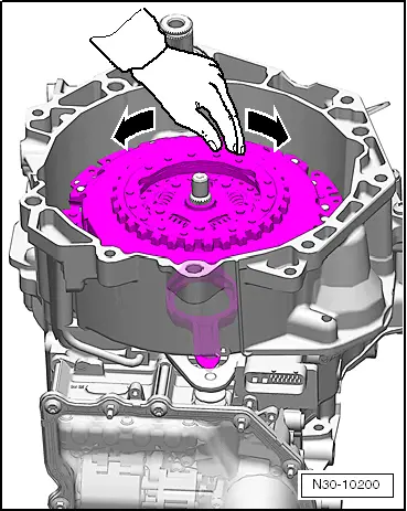
–  Press the clutch downwards via the spindle.
  Note
t  
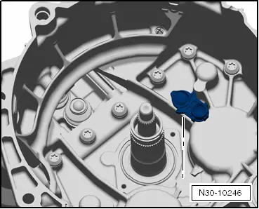
During press-in procedure, place a hand onto the clutch. A slight rattling can be felt. Rattling means that the clutch is pressed into its fitting position. In this way, it can be »detected« if the clutch is pressed in up to the stop.
t  
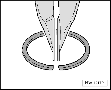
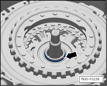
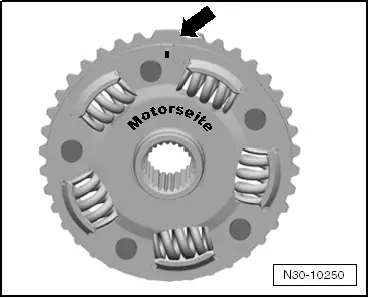
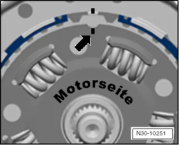
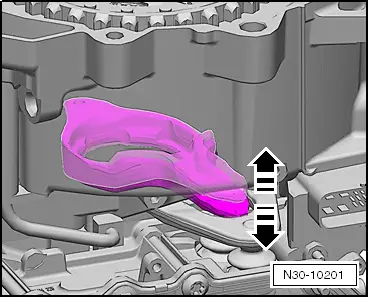
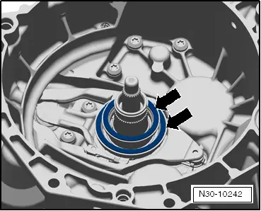
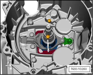
The clutch is pressed in up to the stop if the circlip can be inserted.
  S30-0198
Fitting position of the circlip: the joint of the circlip is »smaller at the top«.
  N30-10172
–  Insert the new circlip -arrow-.
  N30-10238
–  Turn the clutch against the extractor by hand so that the clutch is thus located in its fitting position.
l  Only turn the clutch by hand, do not use any tool.
  N30-10275
Only turn by hand. In this way, the clutch slips against the circlip. Do not use any further tool.
By pressing on the »clutch it is positioned at the bottom« on the drive shaft. The clutch should only be pulled up as far as necessary until it touches the circlip.
  N30-10293
Subsequently insert the hub:
The hub has a »large« tooth and therefore only fits in one position.
On the -engine side-, the »large« tooth has a marking -arrow-.
  N30-10250
–  Install the hub with the marking on the »large tooth« in such a way that it is flush with the marking on the drive plate -arrow-.
  N30-10251
–  Insert the circlip for the hub -arrow-.
Fitting location: The joint of the ring must point to the »lug« on the clutch.
  N30-10233
–  Turn the clutch by hand and while turning it pay attention to the »small« engaging lever.
  N30-10200
While doing so, the engaging lever »in standstill« must remain in its position. It must neither move up nor down.
If the engaging lever moves up and down, the adjusting washers are not in their correct position.
  N30-10201
–  In this case, remove the clutch again → Chapter.
–  Have a close look at the adjusting washers -arrows-.
l  The washers must be correctly positioned. They should not be damaged.
  N30-10242
–  Remove the screw plugs and position both ventilation caps -arrows- again.
Perform the basic setting after the gearbox has been fitted with the → Vehicle diagnostic tester.
  N30-10235

Install the double clutch "new design" as of 06.11 > < Adjust the position of the engaging bearings for clutch "K 1 and K 2" - "new design" as of 06.11