skoda Workshop Repair Guides

Skoda Workshop Service and Repair Manuals

Vehicle electrics > < Setting the secondary shaft
Setting the crown wheel
(Adjusting the differential gear)
Special tools and workshop equipment required
t  
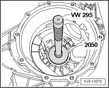
Drift -MP3-403 (VW 295)-
t  
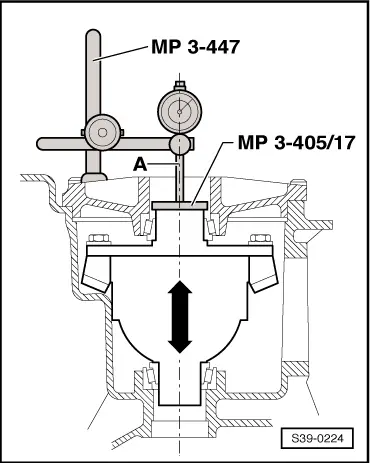
Gauge block plate -MP3-405/17 (VW 385/17)-
t  
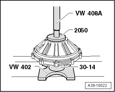
Pressure plate -MP3-407 (VW 402)-
t  
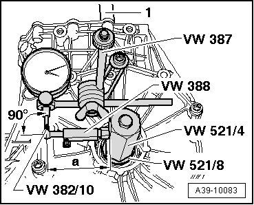
Universal dial gauge holder -MP3-447 (VW 387)-
t  Thrust piece -MP3-448 (VW 408A)-
t  
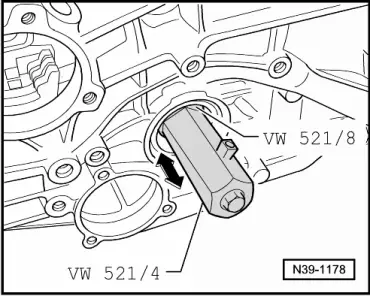
Pipe section -MP3-462/4 (VW 521/4)-
t  Bushing -MP3-462/8 (VW 521/8)-
t  Pressure pipe -MP6-408 (30-14)-
t  Dial gauge extension -VW 382/10-
t  Gauge handle, adjustable -T30014 (VW 388)-
t  Pressure plate -T30042 (2050)-
t  Dial gauge
t  Dial gauge extension 30 mm
The crown wheel must be re-set when the following components are replaced:
Gearbox housing, final drive cover, differential gear tapered roller bearings, differential gear housing, or drive train.
Setting overview → Chapter
Determine overall washer thickness “Stot.” for the adjusting washers “S1” + “S2
(Pre-load setting of tapered roller bearing for differential)
l  Secondary shaft removed.
l  If only the tapered roller bearing for differential was replaced, the crown wheel can be removed from the differential housing. The secondary shaft does not need to be removed.
–  Removing the gasket rings for flange shafts.
–  Remove outer rings/tapered roller bearing for differential and take out the adjusting washers → Chapter.
   
–  Insert outer ring for right tapered roller bearing with adjusting washer “S2” in the gearbox housing. For measuring, use adjusting washer “S2*”, thickness 1.30 mm (2 washers of thickness 0.65 mm).
  Note
As part of the measuring procedure, a temporary adjusting washer “S2” with a thickness of 1.30 mm is inserted. On the following pages, this will be referred to as “S2*”. After measuring the interlocking clearance, the adjusting washer “S2*” is replaced by permanent adjusting washer “S2”.
  A39-10076
–  Press outer ring of left tapered roller bearing without washer “S1” into the final drive cover.
–  Insert the differential gear in the gearbox housing. The crown wheel is on the left side in front of the final drive cover.
l  The O-ring is inserted into the final drive cover.
–  Place the final drive cover and tighten the 4 bolts crosswise to 24 Nm.
–  Turn the gearbox so that the final drive cover is facing upwards.
–  Turn the differential 5 revolutions in both directions, so that the tapered roller bearings can settle.
–  Set gauge block plate -MP3-405/17 (VW 385/17) - on the differential gear.
  A39-10022
–  Mount the measuring tool, use dial gauge extension 30 mm.
–  Set dial gauge (3 mm measuring range) -A- to “0” with a 2 mm bias.
  Note
The measuring tip of the dial gauge must be positioned in the middle of the differential.
–  Raise the differential without turning and read off the play indicated on the dial gauge and note down.
l  Measurement in following example: 0.62 mm
  Note
  S39-0224
t  To raise the differential, attach pipe section -VW 521/4 (MP3-462/4)- with bushing -VW 521/8 (MP3-462/8)- to the right of the differential (housing side).
t  If the measurement has to be repeated, the differential must be turned again 5 revolutions in both directions, so that the tapered roller bearings can settle.
Formula: “Stot” = “S2*” + measured value + bearing pre-load
  N39-1178
Example: 
 Inserted washer (s) “S2*”1.30 mm
+measured value0.62 mm
+Bearing pre-load (constant value)0.30 mm
=Overall washer thickness “Stot” for “S1” + “S22.22 mm

Determining the thickness of adjusting washer “S1*”
  Note
t  After measuring the interlocking clearance, the temporary adjusting washer “S1*” is replaced by the permanent adjusting washer “S1”.
t  Overall washer thickness “Stot.” is unchanged.
Formula: “S1*” = “Stot” - “S2*”
   
Example: 
 Overall washer thickness “Stot” for “S1” + “S22.22 mm
-inserted washer(s) “S2*”1.30 mm
=Thickness of adjusting washer “S1*”0.92 mm

Assign the adjusting washers via → Electronic Catalogue of Original Parts.
Measuring interlocking clearance
l  Secondary shaft installed with adjusting washers “S3” and “S4”.
l  The O-ring is inserted into the final drive cover.
–  Install differential with crown wheel: “S1” is on cover side, “S1” is installed in gearbox housing.
–  Place the final drive cover and tighten the 4 bolts crosswise to 24 Nm.
–  Insert with pipe section -VW 521/4 (MP3-462/4)- with bushing -VW 521/8 (MP3-462/8)-.
–  Turn the differential 5 revolutions in both directions, so that the tapered roller bearings can settle.
   
–  Attach universal dial gauge holder -VW 387(MP3-447)- to gearbox housing.
–  Insert dial gauge with dial gauge extension -VW 382/10- (6 mm flat).
–  Set gauge handle -VW 388 (T30014)- to measurement “a” = 75 mm (for crown wheel Ø 186 mm).
–  Gear tooth flank clearance is measured as follows:
–  Turn crown wheel till one tooth flank fits tightly (end of clearance).
–  Set the dial gauge to “0” with 2 mm bias.
–  Turn crown wheel back until the other tooth flank fits tightly (interlocking clearance).
–  Read off the interlocking clearance value, and note down.
–  Turn the crown wheel through 90° three times, repeating the above measurements each time.
  Note
If the secondary shaft -1- turns during the measurement, counterhold the secondary shaft so that an exact interlocking clearance can be measured.
Determine average interlocking clearance
–  Add the 4 measured values and divide the total by 4.
  A39-10083
Example: 
 1st measured value0.28 mm
+2nd measured value0.30 mm
+3rd measured value0.30 mm
+4th measured value0.28 mm
=Total of the measured values1.16 mm

l  Result: The average interlocking clearance is 1.16 mm : 4 = 0.29 mm.
  Note
If individual measured values deviate more than 0.06 mm from each other, then the crown wheel setting (or the crown wheel itself) is not correct. Check the assembly work, and replace the drive train if necessary.
Determining the thickness of adjusting washer “S2
Formula: “S2” = “S2*” - measured interlocking clearance + nominal interlocking clearance
   
Example: 
 Inserted adjusting washer “S2*”1.30 mm
-measured interlocking clearance0.29 mm
+Nominal interlocking clearance0.15 mm
=Thickness of adjusting washer “S21.16 mm

–  Determine the adjusting washer (s) according to the table. Part numbers → Electronic Catalogue of Original Parts.
Available adjusting washers for “S2
   
Adjusting washer thickness (mm)
0,450,610,77
0,490,650,81
0,530,690,85
0,570,73 

Each random thickness can be determined by the tolerances of the adjusting washers, if necessary insert 2 washers.
Determining the thickness of adjusting washer “S1
Formula: “S1” = “Stot” - “S2
   
Example: 
 Overall washer thickness “Stot” for “S1” + “S22.22 mm
-Thickness of adjusting washer “S21.16 mm
=Thickness of adjusting washer “S11.06 mm

–  Determine the adjusting washer (s) according to the table. Part numbers → Electronic Catalogue of Original Parts.
Available adjusting washers for “S1
   
Adjusting washer thickness (mm)
0,450,610,77
0,490,650,81
0,530,690,85
0,570,73 

Each random thickness can be determined by the tolerances of the adjusting washers, if necessary insert 2 washers.
   
Control measurement
–  After installing the adjusting washers “S1” and “S2”, turn the differential 5 revolutions in both directions, so that the tapered roller bearings can settle.
–  Measure interlocking clearance 4 times at circumference.
t  Specified value: 0.12…0.22 mm
  Note
t  If the secondary shaft -1- turns during the measurement, counterhold the secondary shaft so that an exact interlocking clearance can be measured.
t  If the interlocking clearance is outside the tolerance, the adjusting work must be repeated. The overall washer thickness “Stot” must not be changed.
t  The individual measured values may only deviate max. 0.06 mm from one another.
  A39-10083

Vehicle electrics > < Setting the secondary shaft