
Manual Gearbox 01E Drive Shaft Operation
 Note
Note
|
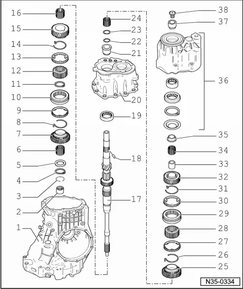
| 1 - | Gearbox housing |
| q | repairing → Chapter |
| 2 - | Needle bushing |
| q | for drive shaft |
| q | extracting and driving in → Chapter |
| 3 - | Circlip |
| q | for needle bushing |
| 4 - | Circlip |
| q | for drive shaft |
| 5 - | Thrust washer |
| 6 - | Needle bearing |
| q | for 4th gear |
| q | identify before removing |
| q | not to be confused with needle bearing for 3rd gear |
| q | lubricate with gear oil before installing |
| 7 - | 4th gear sliding gear |
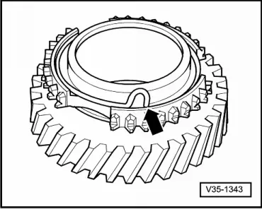
| 8 - | Spring |
| q | place in the 4th gear sliding gear Pos. 7 → Fig. |
| q | Assignment to sliding gear → Electronic Catalogue of Original Parts |
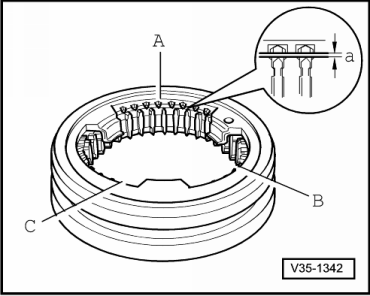
| 9 - | 4th gear synchronizer ring |
| q | check for wear → Fig. |
| 10 - | Sliding sleeve 3rd and 4th gear |
| q | is paired with synchronizer body Pos. 12 |
| q | identify before removing → Chapter |
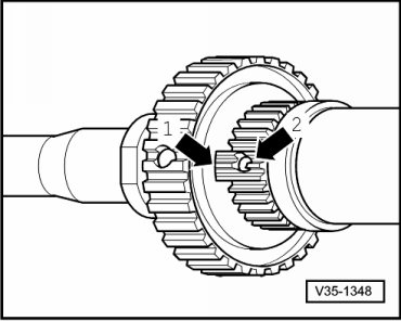
| 11 - | Circlip |
| q | If replacing the synchronizer body Pos. 12, determine thickness of circlip again → Fig. |
| q | Fitting position: ends in line with groove in synchronizer body |
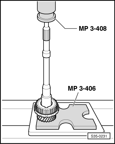
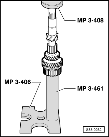
| 12 - | Synchronizer body for 3rd and 4th gear |
| q | pressing off → Fig. |
| q | Fitting position → Fig. |
| q | pressing on → Fig. |
| 13 - | 3rd gear synchronizer ring |
| q | coated with molybdenum |
| q | check for wear → Fig. |
| 14 - | Spring |
| q | insert in the 3rd gear sliding gear Pos. 15 → Fig. |
| q | Assignment to sliding gear → Electronic Catalogue of Original Parts |
| 15 - | 3rd gear sliding gear |
| 16 - | Needle bearing |
| q | for 3rd gear |
| q | identify before removing |
| q | not to be confused with needle bearing for 4th gear |
| q | lubricate with gear oil before installing |
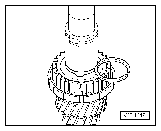
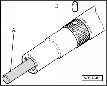
| 17 - | Drive shaft |
| 18 - | Tensioning sleeve |
| q | always replace → Electronic Catalogue of Original Parts |
| q | insert when replacing the drive shaft → Fig. |
| 19 - | Cylindrical-roller bearing |
| q | for drive shaft |
| q | pressing in and pressing out → Chapter |
| 20 - | Bearing shield |
| q | repairing → Chapter |
| 21 - | Inner ring |
| q | for cylindrical-roller bearing |
| q | position/remove manually |
| 22 - | Circlip |
| 23 - | Thrust washer |
| q | for needle bearing for 6th gear sliding gear |
| q | Fitting position: Collar for circlip, smooth thrust surface for needle bearing → Chapter |
| 24 - | Needle bearing |
| q | for 6th gear |
| q | lubricate with gear oil before installing |
| 25 - | 6th gear sliding gear |
| q | after installing, check axial play with feeler gauge (0.15...0.35 mm) |
| 26 - | Spring |
| q | insert in the 6th gear sliding gear Pos. 25 → Fig. |
| q | Assignment to sliding gear → Electronic Catalogue of Original Parts |
| 27 - | 6th gear synchronizer ring |
| q | check for wear → Fig. |
| 28 - | Synchronizer body for 5th and 6th gear |
| q | xtracting and inserting → Chapter |
| q | Fitting position: projecting hub towards 5th gear sliding gear |
| 29 - | Sliding sleeve 5th and 6th gear |
| q | is paired with synchronizer body Pos. 28 |
| q | identify before removing → Chapter |
| 30 - | 5th gear synchronizer ring |
| q | check for wear → Fig. |
| 31 - | Spring |
| q | insert in the 5th gear sliding gear Pos. 32 → Fig. |
| q | Assignment to sliding gear → Electronic Catalogue of Original Parts |
| 32 - | 5th gear sliding gear |
| 33 - | Inner ring for needle bearing |
| q | for 5th gear sliding gear |
| q | xtracting and inserting → Chapter |
| 34 - | Needle bearing |
| q | for 5th gear |
| q | lubricate with gear oil before installing |
| 35 - | 1st Inner ring for four-point bearing |
| q | Ball bearing side |
| q | xtracting and inserting → Chapter |
| 36 - | Cover |
| q | repairing → Chapter |
| 37 - | 2nd inner ring for four-point bearing |
| q | Roller bearing side |
| q | xtracting and inserting → Chapter |
| 38 - | Splined nut, 150 Nm |
| q | slacken and tighten → Chapter |
|
|
Note
|
|
| Circlip thickness (mm) | ||
| 1,90 | 1,96 | 2,02 |
| 1,93 | 1,99 | 2,05 |
|
|
|
|
|
|
|
|