
WIRING DIAGRAM - Toyota Hilux AN120/AN130 2015-2018 Workshop Manual
- Make
- Toyota
- Model
- Hilux Toyota Hilux AN120/AN130 2015-2018 Workshop Manual
- Section
- ECM Power Source Circuit › WIRING DIAGRAM - Toyota Hilux AN120/AN130 2015-2018 Workshop Manual
‹ Prev ii. Remove the EFI-B fuse from the No. 1 engine room relay - Toyota Hilux AN120/AN130 2015-2018 Workshop ManualNext › CAUTION / NOTICE / HINT - Toyota Hilux AN120/AN130 2015-2018 Workshop Manual
ECD SYSTEMWIRING DIAGRAM - Toyota Hilux AN120/AN130 2015-2018 Workshop Manual
WIRING DIAGRAM
1GD-FTV ENGINE CONTROL ECD SYSTEM ECM Power Source Circuit DESCRIPTION
When the ignition switch is turned to ON, the battery voltage is applied to terminal IGSW of the ECM. The MREL output signal from ECM causes a current to flow to the coil, closing the contacts of the EFI-MAIN NO. 1 relay and supplying power to terminal +B of the ECM.
WIRING DIAGRAM
w/ Entry and Start System
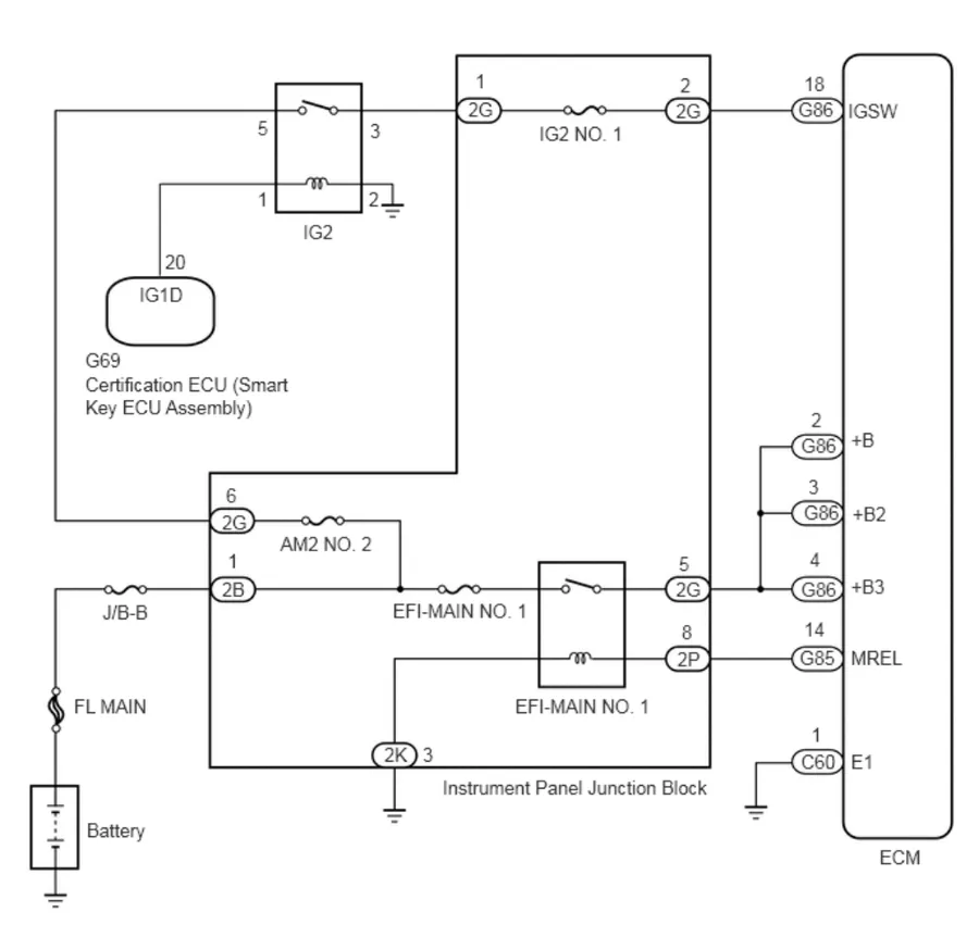
w/o Entry and Start System
‹ Prev ii. Remove the EFI-B fuse from the No. 1 engine room relay - Toyota Hilux AN120/AN130 2015-2018 Workshop ManualNext › CAUTION / NOTICE / HINT - Toyota Hilux AN120/AN130 2015-2018 Workshop Manual
Parts & tools for this job For Toyota Hilux
- TOOLDigital multimeterSearch: automotive digital multimeter
- PARTAssorted fuse kitSearch: car fuse assortment kit
- TOOLWire crimper and connector kitSearch: wire crimper connector kit
As an Amazon Associate we earn from qualifying purchases.