
WIRING DIAGRAM - Toyota Hilux AN120/AN130 2015-2018 Workshop Manual
- Make
- Toyota
- Model
- Hilux Toyota Hilux AN120/AN130 2015-2018 Workshop Manual
- Section
- VC Output Circuit › WIRING DIAGRAM - Toyota Hilux AN120/AN130 2015-2018 Workshop Manual
‹ Prev Turbocharger Oil Leak and White Smoke: 7.CHECK TURBOCHARGER - Toyota Hilux AN120/AN130 2015-2018 Workshop ManualNext › VC Output Circuit - Toyota Hilux AN120/AN130 2015-2018 Workshop Manual
ECD SYSTEMWIRING DIAGRAM - Toyota Hilux AN120/AN130 2015-2018 Workshop Manual
WIRING DIAGRAM
1GD-FTV ENGINE CONTROL ECD SYSTEM VC Output Circuit DESCRIPTION
The ECM constantly generates a 5 V power source voltage from the battery voltage supplied to the +B (BATT) terminal to operate the microprocessor. The ECM also provides this power source voltage to the sensors through the VC output circuit.
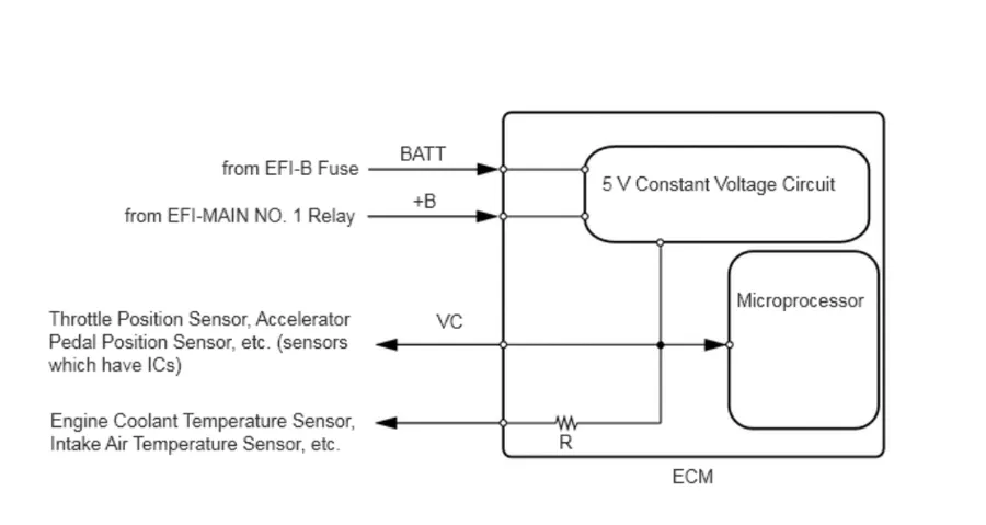
When the VC circuit has a short circuit, the CPU in the ECM and sensors that are supplied power through the VC circuit are deactivated because power is not supplied from the VC circuit. When the system is in this condition, it will not start.
WIRING DIAGRAM
· For the circuit diagram of the ECM power source circuit.
· VC Power Source Circuit
‹ Prev Turbocharger Oil Leak and White Smoke: 7.CHECK TURBOCHARGER - Toyota Hilux AN120/AN130 2015-2018 Workshop ManualNext › VC Output Circuit - Toyota Hilux AN120/AN130 2015-2018 Workshop Manual
Parts & tools for this job For Toyota Hilux
- TOOLDigital multimeterSearch: automotive digital multimeter
- PARTAssorted fuse kitSearch: car fuse assortment kit
- TOOLWire crimper and connector kitSearch: wire crimper connector kit
As an Amazon Associate we earn from qualifying purchases.