|
Components of the Alternator, Check
 Clean Clean
|
Clean individual alternator parts with cleaning petrol –
only short contact time permitted.
 Inspect
Check ball bearing – replace if necessary.
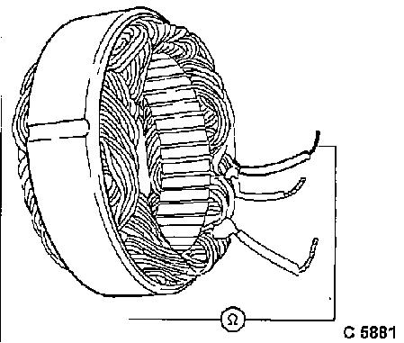
Check phases of the stator winding for short circuit to ground:
use ohmmeter, nominal value: resistance infinite.
Replace stator with short circuit to ground.
|
|
|
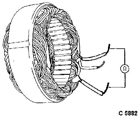
Check phases of the stator winding for winding short circuit.
Use ohmmeter. Resistance of two phases compared – see
"Technical Data".
Replace stator with winding short circuit.
|
|
|
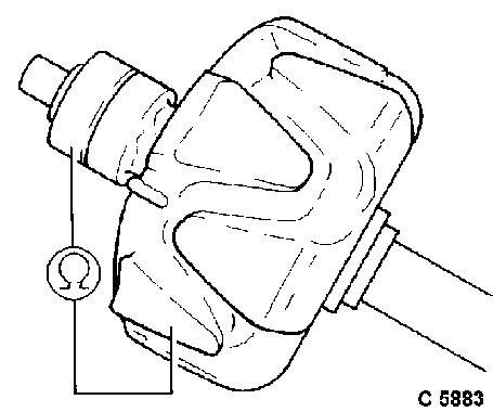
Check rotor winding for short circuit to ground. Use ohmmeter,
nominal value: – resistance infinite.
Replace rotor with short circuit to ground.
|
|
|
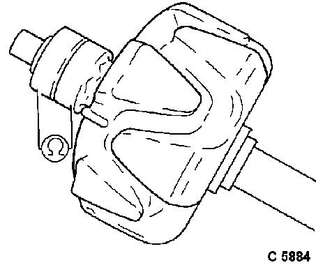
Check rotor winding for winding short circuit. Use ohmmeter.
Resistance of the slip rings compared – see "Technical
Data".
Replace rotors with winding short circuit.
Clean
Disconnect slip rings on lathe – use emery cloths.
Inspect
|
|
|
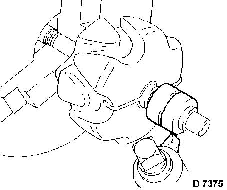
Check slip rings for true running, permissible deviation: 0.03
mm. Twist off slip rings that are not round – do not go below
minimum dimension – see "Technical Data". Polish and clean
slip rings.
|
|
|
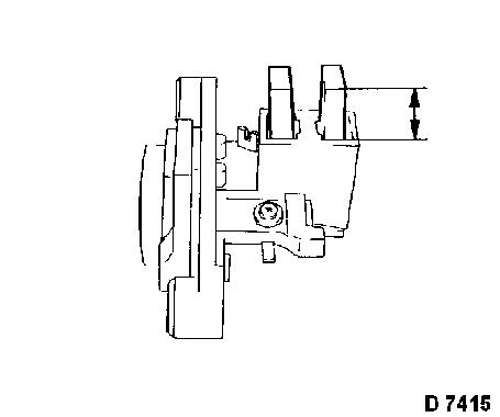
Check carbon brushes for wear.
Replace worn carbon brushes.
|
|
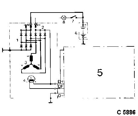
Check diodes: circuit diagram of the electrically controlled
alternator:
| 1. |
Rectifier diode |
| 2. |
Excitation diode |
| 3. |
Stator winding |
| 4. |
Excitation winding |
| 5. |
Electronic voltage regulator (installed) |
| 6. |
Battery |
| 7. |
Ignition lock |
| 8. |
Battery charge telltales |
|
|
|
Check diodes for continuity, defective connections, short
circuits, blocking action: Test result only permits qualitative
statements about the potential and the state of the diode barrier
layer. If an exact test of the diodes is to be performed, then a
diode tester must be used. For defective diodes the complete diode
plate must be replaced. The described test using test lamps is
carried out with a voltage of at most 24 volt.
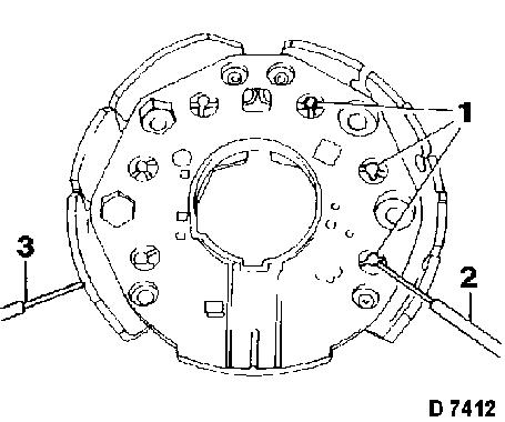
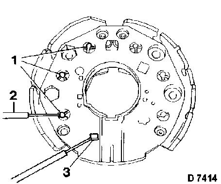
Check negative diodes (1): hold positive probe (2) against diode
casing, negative probe (3) against diode connection – test
lamp must light up. Exchange test probes – test lamp must not
light up. Negative diodes have continuity from casing to
connection, the block in the opposite direction.
|
|
|
Check positive diodes (1): hold positive probe (2) against diode
connection, negative probe (3) against diode casing – test
lamp must light up. Exchange test probes – test lamp must not
light up. Positive diodes have continuity from connection to casing
and block in the opposite direction.
Check excitation diodes (1): hold positive probe (2) against
diode connection, negative probe against contact rails (3) –
test lamp must light up. Exchange test probes – test lamp
must not light up.
|
|
|
