|
Alternator, Check
Note: Check consists
of power check and regulated voltage check, perform power check
first. For simultaneous rating of electronic components, use
suitable oscilloscope.
The test can be carried out both in the installed state and on
the test bench. The test is described below for the installed
state, the test on the test bench is performed analogously.
A charged battery is necessary for the test.
Caution
Note following safety measures:
| 1. |
Negative terminal from battery, alternator and
regulator must correspond. |
| 2. |
Never allow the alternator to run in an
uncontrolled open circuit. |
| 3. |
Never short-circuit the terminals to the alternator
and regulator. |
| 4. |
Never reverse polarity of alternator. |
| 5. |
For connection to an additional battery (e.g.
starting aid) ensure that the same battery terminals are connected
to one another. |
| 6. |
When charging the battery pay attention to polarity
of the connection terminals of the charger. During the charging
operation in the installed state, the ground lead must be
disconnected. |
 Inspect
|
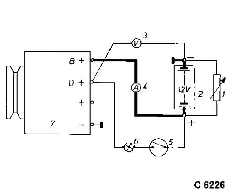
Alternator Power, Check:
Circuit diagram:
| 1. |
Load resistor connected in parallel to the
battery |
| 2. |
Battery |
| 3. |
Voltmeter |
| 4. |
Ammeter |
| 5. |
Ignition lock |
| 6. |
Battery charge telltales |
| 7. |
Alternator |
Disconnect battery, disconnect connecting cable from the
alternator terminal "B+". Connect ammeter (measuring range 100 A)
into disconnected line.
Connect adjustable load resistor to battery terminals. Set
resistance before the connection to "0". First connect to battery,
then to resistor. Connect rpm gauge. Connect oscilloscope in
accordance with manufacturer's instructions. Connect battery.
Start motor and read off generated current at different rpm.
|
|
|
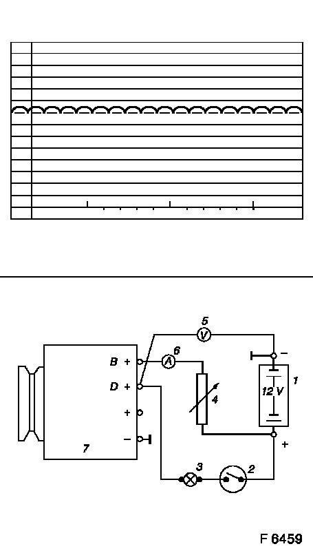
Alternator Power, Check:
Adjust load resistance if the required load currents are not
achieved. The shape of the voltage curves on the oscilloscope
should be uniform. Test value: 5 to 7 A.
If the required minimum current intensities are not achieved or
if the oscilloscope indicates deviations, then the alternator must
be overhauled.
Regulated voltage: circuit diagram
| 1. |
Battery |
| 2. |
Ignition lock |
| 3. |
Battery charge telltales |
| 4. |
Resistor, connected in series to the battery to
obtain the load current |
| 5. |
Voltmeter |
| 6. |
Ammeter |
| 7. |
Alternator |
|
|
Regulated Voltage, Check:
Connect rpm gauge, voltmeter / ammeter and load resistor in
accordance with manufacturer's instructions.
Disconnect battery. Disconnect cable from alternator terminal
"B+". Connect ammeter (measuring range 100 A) between disconnected
cable and alternator terminal "B+". Connect resistor in series to
battery.
Start motor. Adjust load resistance until the ammeter indicates
the prescribed value. Read off regulated voltage – for test
values see "Technical Data".
Caution
Check alternator only with parallel-connected, fully charged
battery, only switch off load resistor and battery once the
alternator is at a standstill.
Switching off load with battery not connected in parallel
generates voltage peaks which may lead to the destruction of the
alternator diodes.
|
