BrakesBrake Pipe Replacement
Brake Pipe Replacement
Special Tools
CH-45405 Pipe Flaring Tool Kit
For equivalent regional tools, refer to
Special Tools .
Warning: Refer to
Brake Fluid Irritant Warning .
|
Warning:
Always use double walled steel brake pipe when
replacing brake pipes. The use of any other pipe is not recommended
and may cause brake system failure. Carefully route and retain
replacement brake pipes. Always use the correct fasteners and the
original location for replacement brake pipes. Failure to properly
route and retain brake pipes may cause damage to the brake pipes
and cause brake system failure. |
Caution: Refer to
Brake Fluid Effects on Paint and Electrical
Components Caution .
Note: When servicing the
brake pipes, note the following:
| • |
If sectioning the
brake pipe, use replacement pipe of the same type and outside
diameter. |
| • |
Use fittings of
the appropriate size and type. |
| • |
Only create flares
of the same type or design as originally equipped on the
vehicle. |
| 1. |
Inspect the area of brake pipe
to be repaired or replaced. |
| 2. |
Release the brake pipe to be
replaced from the retainers, as required. |
| 3. |
Select an appropriate location
to section the brake pipe, if necessary. |
| |
• |
Allow adequate clearance in
order to manoeuvre the CH-45405 flaring tool
. |
| |
• |
Avoid sectioning the brake
pipe at bends or mounting points. |
| 4. |
Using a string or wire,
measure the length of the pipe to be replaced including all pipe
bends. |
| 5. |
Add to the measurement taken
the appropriate additional length required for each flare to be
created. |
Specification
| • |
6.35 mm (0.250
in) for 4.76 mm (3/16 in) diameter
pipe |
| • |
9.50 mm (0.374
in) for 6.35 mm (1/4 in) diameter
pipe |
| • |
12.67 mm (0.499
in) for 7.94 mm (5/16 in) diameter
pipe |
|
Note: Ensure that the
brake pipe end to be flared is cut at a square, 90
degree angle to the pipe length.
|
| 6. |
Using the pipe cutter included
in the CH-45405 flaring tool , carefully cut the
brake pipe squarely to the measured length. |
| 7. |
Remove the sectioned brake
pipe from the vehicle. |
| 8. |
Select the appropriate size of
brake pipe and tube nuts, as necessary. The brake pipe outside
diameter determines brake pipe size. |
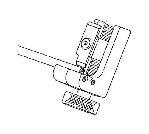
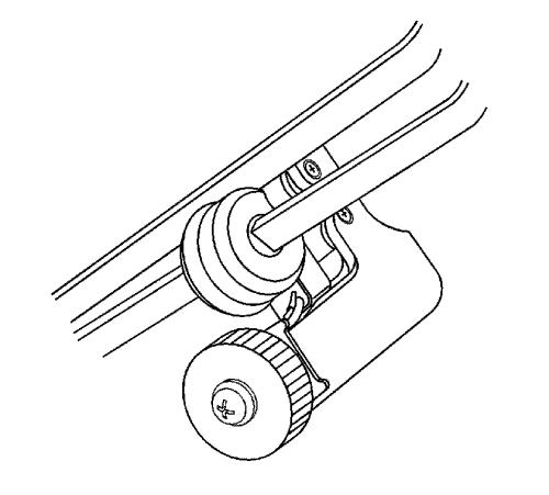
| 9. |
Strip the nylon coating from
the brake pipe end to be flared, if necessary. |
| |
• |
Select the appropriate blade
on the coating stripping tool included in the CH-45405
flaring tool , by unthreading the blade block from the
stripping tool and installing the block with the desired blade
facing the tool rollers. |
Specification
| |
- |
6.35 mm (0.250 in) blade for
4.76 mm (3/16 in) diameter pipe |
| |
- |
9.50 mm (0.374 in) blade for
6.35 mm (1/4 in) and 7.94 mm
(5/16 in) diameter pipe |
| |
• |
Insert the brake pipe end to
be flared into the stripping tool to the depth of the ledge on the
tool rollers. |
| |
|
|
| |
• |
While holding the brake pipe
firmly against the stripping tool roller ledges, rotate the
thumbwheel of the tool until the blade contacts the brake pipe
coated surface. |
|
Note: Do not gouge the
metal surface of the brake pipe.
|
| |
• |
Rotate the stripping tool in a
clockwise direction, ensuring that the brake pipe end remains
against the tool roller ledges. |
| |
• |
After each successive
revolution of the stripping tool, carefully rotate the thumbwheel
of the tool clockwise, in order to continue stripping the coating
from the brake pipe until the metal pipe surface is exposed.
|
| |
|
|
| |
• |
Loosen the thumbwheel of the
tool and remove the brake pipe. |
|
Note: Ensure that all loose
remnants of the nylon coating have been removed from the brake
pipe.
|
| |
• |
Inspect the stripped end of
the brake pipe to ensure that the proper amount of coating has been
removed. |
Specification
| |
- |
6.35 mm (0.250 in) for
4.76 mm (3/16 in) diameter pipe |
| |
- |
9.50 mm (0.374 in) for
6.35 mm (1/4 in) and 7.94 mm
(5/16 in) diameter pipe |
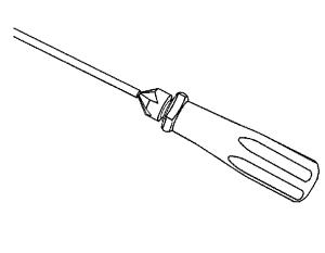
| 10. |
Chamfer the inside and outside
diameter of the pipe with the de-burring tool included in the
CH-45405 flaring tool . |
| 11. |
Install the tube nuts on the
brake pipe, noting their orientation. |
| 12. |
Clean the brake pipe and the
CH-45405 flaring tool of lubricant, contaminants,
and debris. |
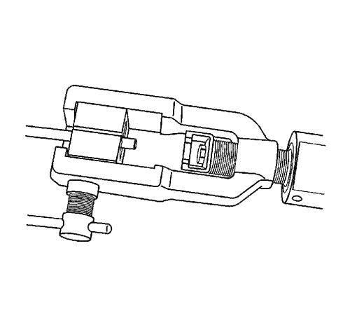
| 13. |
Loosen the die clamping screw
of the CH-45405 flaring tool . |
| 14. |
Select the corresponding die
set and install the die halves into the die cage with the full,
flat face of one die facing the clamping screw, and the
counterbores of both dies facing the forming ram. |
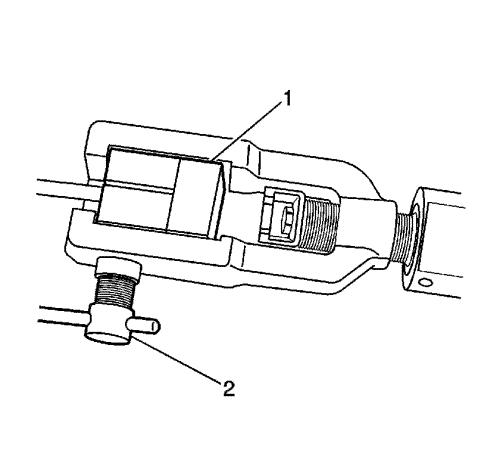
| 15. |
Place the flat face of an
unused die (1) against the die halves in the clamping cage and hold
firmly against the counterbored face of the dies. |
| 16. |
Insert the prepared end of the
pipe to be flared through the back of the dies until the pipe is
seated against the flat surface of the unused die (1). |
| 17. |
Remove the unused die
(1). |
| 18. |
Ensure that the rear of both
dies are seated firmly against the enclosed end of the die
cage. |
| 19. |
Firmly hand tighten the
clamping screw (2) against the dies. |
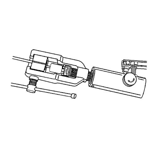
| 20. |
Select the appropriate forming
mandrel and place into the forming ram. |
| 21. |
Rotate the hydraulic fluid
control valve clockwise to the closed position. |
| 22. |
Rotate the body of the
CH-45405 flaring tool until it bottoms against the
die cage. |
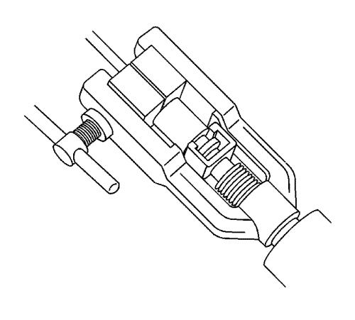
| 23. |
While guiding the forming
mandrel into the exposed end of pipe to be flared, operate the
lever of the CH-45405 flaring tool until the
forming mandrel bottoms against the clamping dies. |
| 24. |
Rotate the hydraulic fluid
control valve counterclockwise to the open position to allow the
hydraulic forming ram to retract. |
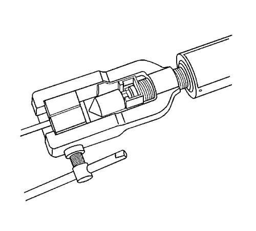
| 25. |
Insert the finishing cone into
the forming ram. |
| 26. |
Rotate the hydraulic fluid
control valve clockwise to the closed position. |
| 27. |
Rotate the body of the
CH-45405 flaring tool until it bottoms against the
die cage. |
| 28. |
While guiding the finishing
cone into the exposed end of pipe to be flared, operate the lever
of the CH-45405 flaring tool until the finishing
cone bottoms against the dies. |
| 29. |
Rotate the hydraulic fluid
control valve counterclockwise to the open position to allow the
hydraulic forming ram to retract. |
| 30. |
Loosen the die clamping screw
and remove the dies and pipe. |
| 31. |
If necessary, lightly tap the
dies until the die halves separate. |
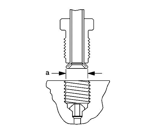
| 32. |
Inspect the brake pipe flare
for correct shape and diameter (a). |
Specification
| • |
6.74-7.10 mm
(0.265-0.279 in) flare diameter for 4.76 mm
(3/16 in) diameter pipe |
| • |
8.57-9.27 mm
(0.344-0.358 in) flare diameter for 6.35 mm
(1/4 in) diameter pipe |
| • |
10.42-10.79 mm
(0.410-0.425 in) flare diameter for 7.94 mm
(5/16 in) diameter pipe |
| 33. |
If necessary, using the
removed section of brake pipe as a template, shape the new pipe
with a suitable brake pipe bending tool. |
|
Note: When installing
the pipe, maintain a clearance of 19 mm (3/4
in) from all moving or vibrating components.
|
| 34. |
Install the pipe to the
vehicle with the appropriate brake pipe unions, as required.
|
| 35. |
If previously released, secure
the brake pipe to the retainers. |
| 37. |
With the aid of an assistant,
inspect the brake pipe flares for leaks by starting the engine and
applying the brakes. |
|
|
07 Brakes
