
Engine Replacement
- Make
- Vauxhall
- Model
- Astra J
- Section
- Engine mechanics - 1.3L Diesel › Repair Instructions - On Vehicle › Engine Replacement
EngineEngine Replacement
Engine ReplacementSpecial Tools
For equivalent regional tools, refer to Special Tools . Removal Procedure
Warning: Refer to
Gasoline/Gasoline Vapors Warning .
|
| 1. | Remove the lower intermediate steering shaft bolt. Refer to Intermediate Steering Shaft Replacement . |
| 2. | Open the hood. |
| 3. | Remove the engine sight shield. Refer to Engine Sight Shield Replacement . |
| 4. | Recover the refrigerant. Refer to Refrigerant Recovery and Recharging . |
| 5. | Remove the battery tray. Refer to Battery Tray Replacement . |
| 6. | Remove the air cleaner. Refer to Air Cleaner Replacement . |
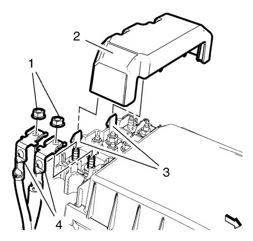
| 7. | Remove the front compartment fuse block housing cover (2). |
| Unclip the 2 retainer clips (3). |
| 8. | Remove the 2 terminal wiring harness nuts (1) from the front compartment fuse block housing. |
| 9. | Remove the 2 terminal wiring harness (4) from the front compartment fuse block housing. |
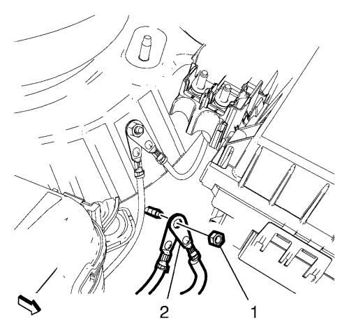
| 10. | Remove the electronic steering pump ground cable nut (1). |
| 11. | Remove the 2 electronic steering pump ground cables (2). |
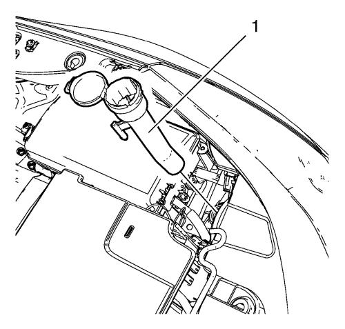
| 12. | Remove the windshield washer solvent container filler tube (1). |
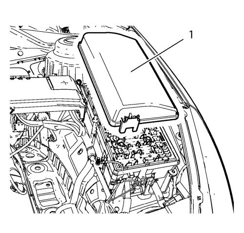
| 13. | Remove the front compartment fuse block cover (1). |
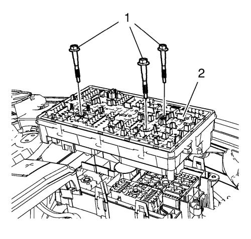
| 14. | Remove the 3 front compartment fuse block bolts (1). |
| 15. | Remove the front compartment fuse block (2). |
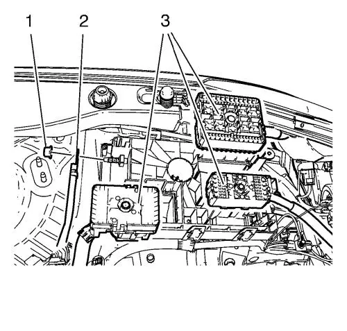
| 16. | Unclip the 3 wiring harness plugs (3). |
| 17. | Disconnect the wiring harness plug from the front compartment fuse block. |
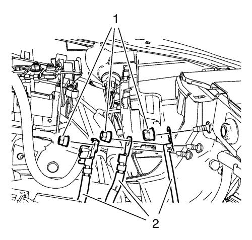
| 18. | Remove the 3 ground nuts (1) and hang the 3 wiring harnesses (2) aside. |
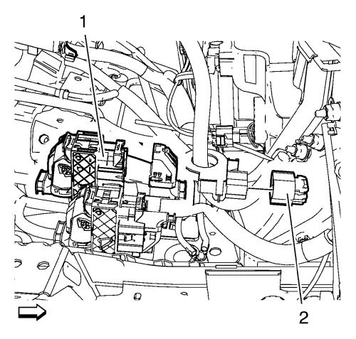
| 19. | Disconnect the 2 wiring harness plugs (1, 2). |
| 20. | Remove the shift lever and the selector lever cable from transmission and transmission shift lever and the selector lever bracket. Refer to Manual Transmission Shift Lever and Selector Lever Cable Replacement . |
| 21. | Remove the shift lever and the selector lever cable from shift lever and the selector lever cable bracket (1). |
| 22. | Place a collecting basin underneath. |
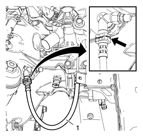
| 23. | Open the retaining clip (arrow). |
| 24. | Disconnect the clutch actuator cylinder front pipe (1) from the clutch actuator cylinder pipe elbow. |
| 25. | Remove the clutch actuator cylinder front pipe. |
| 26. | Remove the front tire and wheel assembly. Refer to Tire and Wheel Removal and Installation . |
| 27. | Remove the front bumper fascia. Refer to Front Bumper Fascia Replacement . |
| 28. | Drain the cooling system. Refer to Cooling System Draining and Filling . |
| 29. | Remove the radiator surge tank. Refer to Radiator Surge Tank Replacement . |
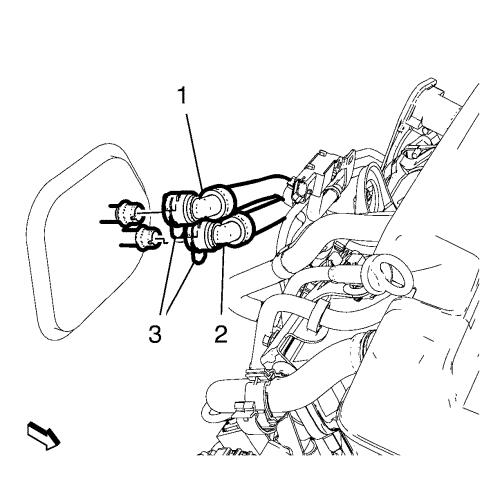
| 30. | Unclip the heater inlet and the outlet hose clamp (3). |
| 31. | Remove the heater inlet hose (1) and heater outlet hose (2) from the bulkhead. |
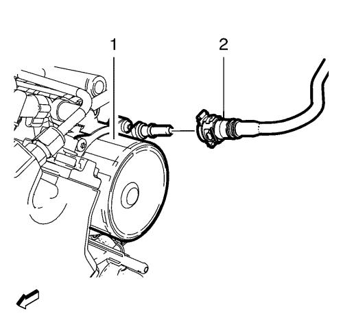
| 32. | Remove the brake booster vacuum pipe (2) from the vacuum pump (1). |
| Disconnect the plastic collar quick connect fitting. Refer to Plastic Collar Quick Connect Fitting Service . |
| 33. | Place a collecting basin underneath. |
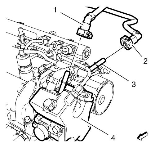
| 34. | Remove the fuel feed pipe (1) from the fuel injection pump (4). |
| Disconnect the plastic collar quick connect fitting. Refer to Plastic Collar Quick Connect Fitting Service . |
| 35. | Remove the fuel return pipe (2) from the fuel separator (3). |
| Disconnect the plastic collar quick connect fitting. Refer to Plastic Collar Quick Connect Fitting Service . |
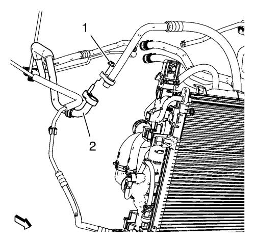
| 36. | Remove the A/C compressor and the condenser hose nut (1) from the refrigerant hose (2). |
| 37. | Remove the right headlamp. Refer to Headlamp Replacement . |
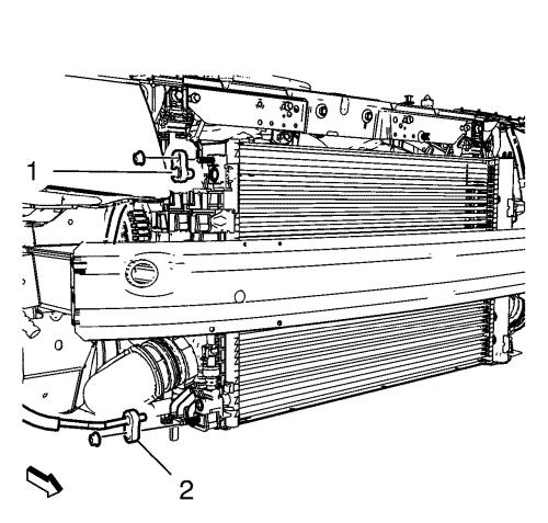
| 38. | Remove the lower and upper condenser hose nuts and the lower and upper condenser hoses (1, 2). |
| 39. | Remove the upper stabilizer shaft link from the absorber on both sides. Refer to Stabilizer Shaft Link Replacement . |
| 40. | Remove the steering linkage outer tie rod from the steering knuckle on both sides. Refer to Steering Linkage Outer Tie Rod Replacement . |
| 41. | Remove the front lower control arm from the steering knuckle. Refer to Lower Control Arm Replacement . |
| 42. | Remove the front wheel shafts from the wheel hubs. Refer to Front Wheel Drive Shaft Replacement - Right Side . |
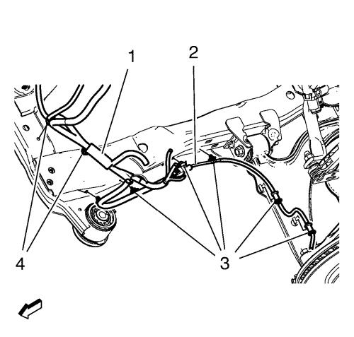
| 43. | Remove the wheel speed sensor wiring harness (2) from the frame on both sides. |
| 44. | Remove the wiring harness retainers (3) from the frame and the lower control arm. |
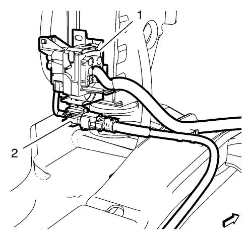
| 45. | Disconnect the coolant fan wiring harness plug (1) and the power steering wiring harness plug (2). |
| 46. | Remove the exhaust front pipe. Refer to Exhaust Front Pipe Replacement . |
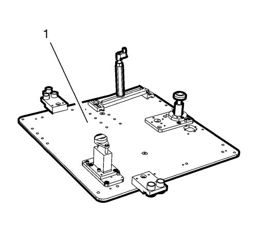
Note: The SPX installation manual is supplied with the special tool and is also available online from SPX directly. Go to www.spxtools-shop.com. |
| 47. | Assemble the CH-49290 engine support tool (1) according to the details provided in the SPX installation manual. |
| 48. | Support the CH-904 base frame on a jack. |
| 49. | Support the CH-49290 engine support tool on the CH-904 base frame . |
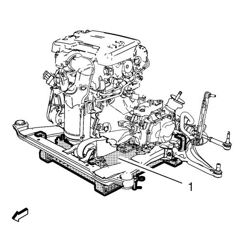
Note: The SPX installation manual is supplied with the special tool and is also available online from SPX directly. Go to www.spxtools-shop.com. |
| 50. | Install the CH-49290 engine support tool (1) according to the details provided in the SPX installation manual. |
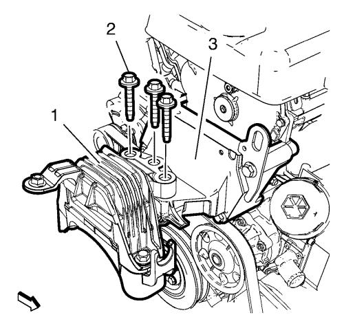
| 51. | Remove the 3 engine mount bolts (2) from the engine mount (1) and the engine mount bracket (3). |
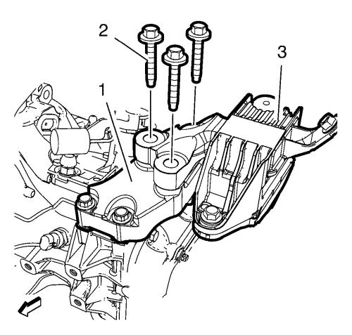
| 52. | Remove the 3 transmission mount bolts (2) from the transmission mount (3) and the transmission mount bracket (1). |
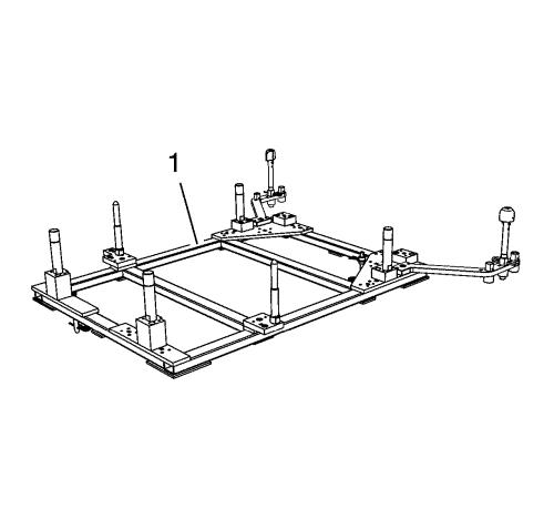
Note: The SPX installation manual is supplied with the special tool and is also available online from SPX directly. Go to www.spxtools-shop.com. |
| 53. | Assemble the CH-49289 centering frame (1) according to the details provided in the SPX installation manual. |
| 54. | Support the CH-904 base frame on a jack. |
| 55. | Support the CH-49289 centring frame on the CH-904 base frame . |
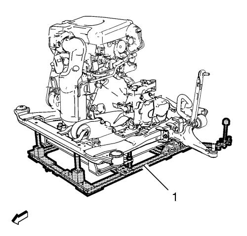
Note: The SPX installation manual is supplied with the special tool and is also available online from SPX directly. Go to www.spxtools-shop.com. |
| 56. | Install the CH-49289 centering frame (1) according to the details provided in the SPX installation manual. |
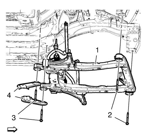
| 57. | Remove the front frame bolts (2). |
| 58. | Remove the rear frame bolts (3). |
| 59. | Remove the frame reinforcements (4). |
| 60. | Lower the frame (1) with the engine transmission unit from the vehicle. |
| 61. | Remove the right wheel drive shaft from the transmission. Refer to Front Wheel Drive Shaft Replacement - Right Side . |
| 62. | Remove the left wheel drive shaft from the transmission. Refer to Front Wheel Drive Shaft Replacement - Left Side . |
| 63. | Remove the upper radiator inlet hose clamp. Refer to Radiator Inlet Hose Replacement . |
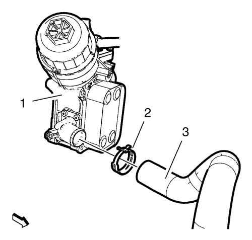
| 64. | Remove the radiator outlet hose clamp (2). |
| 65. | Remove the radiator outlet hose (3) from the engine oil cooler (1). |
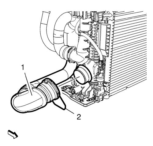
| 66. | Unclip the retainer spring (2). |
| 67. | Remove the charge air cooler inlet air hose (1) from the radiator. |
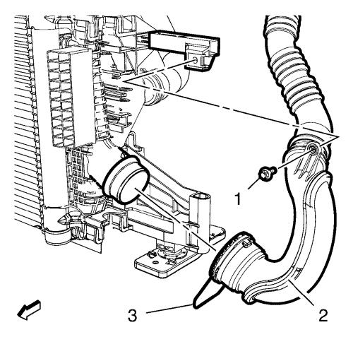
| 68. | Remove the charge air cooler outlet air hose bolt (1) from the radiator lift bracket. |
| 69. | Unclip the retainer spring (3). |
| 70. | Remove the charge air cooler outlet air hose (2) from the radiator. |
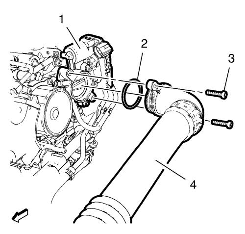
| 71. | Remove the 2 charge air cooler outlet air hose bolts (3). |
| 72. | Remove the charge air cooler outlet air hose bolt from the radiator inlet hose bracket. |
| 73. | Remove the charge air cooler outlet air hose (4) from the throttle body (1). |
| 74. | Remove the charge air cooler outlet air hose seal (2). |
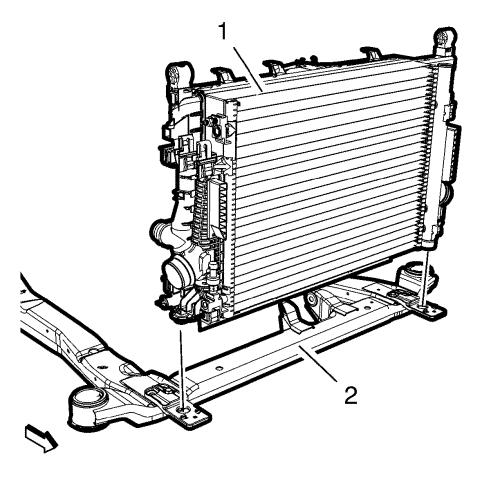
| 75. | Remove the engine coolant radiator (1) from the front suspension (2). |
| 76. | Remove the engine sight shield. Refer to Engine Sight Shield Replacement . |
| 77. | Install a suitable cable to the 3 engine lift brackets. |
| 78. | Install a suitable engine lifting device to the cable. |
| 79. | Extend the engine lifting device until the steel cable are slightly tensioned. |
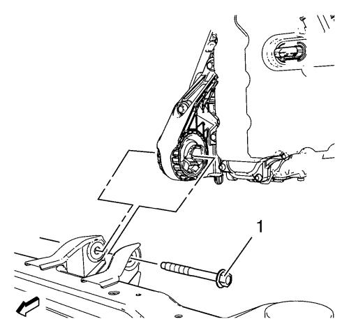
| 80. | Remove the front transmission mount bolt (1). |
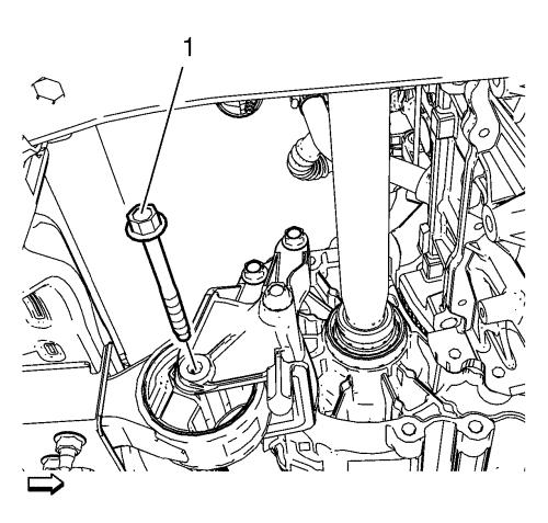
| 81. | Remove the rear transmission bracket mount to mount bolt (1). |
Note: A second technician is required. |
| 82. | Remove the engine transmission unit from the front suspension. |
| 83. | Put the engine transmission unit down on a wooden pallet. |
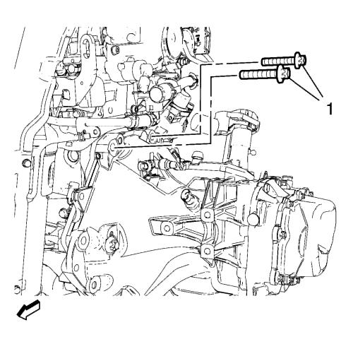
| 84. | Remove the 2 upper transmission bolts (1). |
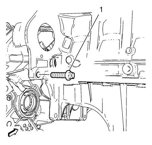
| 85. | Remove the lower transmission bolt (1). |
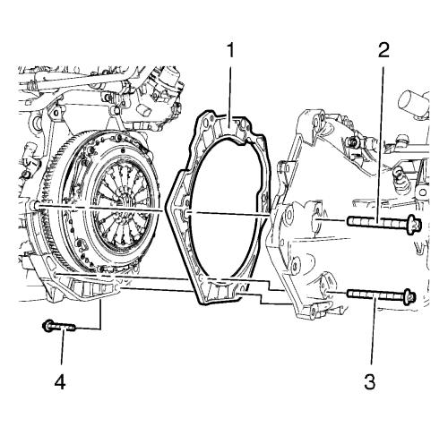
| 86. | Remove the 3 transmission lower bolts (2, 3, 4). |
Note: A second technician is required. |
| 87. | Remove the transmission from engine. |
| 88. | Remove the transmission spacer (1) from the engine. |
| 89. | Remove the clutch pressure and the driven plate. Refer to Clutch Pressure and Driven Plate Replacement . |
| 90. | Install the engine to a suitable engine stand. |
| 91. | Transfer parts as needed. |
Installation Procedure
| 1. | Remove the engine from the engine stand. |
Note: A second technician is required. |
| 2. | Put the engine down on a wooden pallet. |
| 3. | Install the clutch pressure and the driven plate. Refer to Clutch Pressure and Driven Plate Replacement . |
Note: A second technician is required. |
| 4. | Install the transmission to the engine. |
| 5. | Install the transmission spacer (1) to the engine. |
Caution: Refer to Fastener Caution . |
| 6. | Install the 3 transmission lower bolts (3, 4) and tighten to 40 N·m (30 lb ft) . |
| 7. | Install the transmission bolt (2) and tighten to 60 N·m (44 lb ft) . |
| 8. | Install the lower transmission bolt (1) and tighten to 60 N·m (44 lb ft) . |
| 9. | Install the 2 upper transmission bolts (1) and tighten to 60 N·m (44 lb ft) . |
| 10. | Install a suitable cable to the 3 engine lift brackets. |
| 11. | Install a suitable engine lifting device to the cable. |
Note: A second technician is required. |
| 12. | Position the engine transmission unit to the front suspension. |
| 13. | Extend the engine lifting device until the steel cable are slightly tensioned. |
| 14. | Install the rear transmission bracket mount to mount bolt (1) and tighten to 100 N·m (74 lb ft) . |
| 15. | Install the front transmission mount bolt (1) and tighten to 58 N·m (43 lb ft) . |
| 16. | Remove the suitable cable from the 3 engine lift brackets. |
| 17. | Install the engine sight shield. Refer to Engine Sight Shield Replacement . |
| 18. | Install the engine coolant radiator (1) to the front suspension (2). |
| 19. | Instal the NEW charge air cooler outlet air hose seal (2). |
| 20. | Install the charge air cooler outlet air hose (4) to the throttle body (1). |
| 21. | Install the 2 charge air cooler outlet air hose bolts (3) and tighten to 10N·m (89 lb in) . |
| 22. | Install the charge air cooler outlet air hose bolt to the radiator inlet hose bracket and tighten to 10N·m (89 lb in) . |
| 23. | Install the charge air cooler outlet air hose (2) to the radiator. |
| 24. | Clip in the retainer spring (3). |
| 25. | Install the charge air cooler outlet air hose bolt (1) to the radiator lift bracket and tighten to 10N·m (89 lb in) . |
| 26. | Install the charge air cooler inlet air hose (1) to the radiator. |
| 27. | Clip the in retainer spring (2). |
| 28. | Install the radiator outlet hose (3) to the engine oil cooler (1). |
| 29. | Install the radiator outlet hose clamp (2). |
| 30. | Install the upper radiator inlet hose clamp. Refer to Radiator Inlet Hose Replacement . |
| 31. | Install the left wheel drive shaft to the transmission. Refer to Front Wheel Drive Shaft Replacement - Left Side . |
| 32. | Install the right wheel drive shaft to the transmission. Refer to Front Wheel Drive Shaft Replacement - Right Side . |
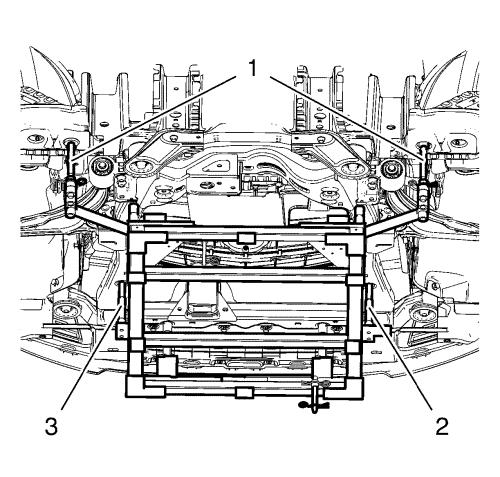
Note: Positioning pins (1) of CH-49289 adapter MUST be extended in order to guide into underbody holes. |
| 33. | Position the frame with the engine transmission unit to the vehicle. |
| 34. | Install the frame reinforcements (3). |
| 35. | Install the frame rear bolts (2). Hand tighten ONLY. |
| 36. | Install the frame front bolts (3). Hand tighten ONLY. |
| 37. | Tighten the rear frame bolts (2) to 160N·m (118 lb ft) . |
| 38. | Tighten the front frame bolts (1) to 160N·m (118 lb ft) . |
| 39. | Lower the CH-49289 centring frame (1) with CH-904 base frame and a jack. |
| 40. | Remove the CH-49289 centring frame from the CH-904 base frame . |
Note: The SPX installation manual is supplied with the special tool and is also available online from SPX directly. Go to www.spxtools-shop.com. |
| 41. | Disassemble the CH-49289 centering frame (1) according to the details provided in the SPX installation manual. |
| 42. | Install the 3 transmission mount bolts (2) to the transmission mount (3) and the transmission mount bracket (1) and tighten to 62 N·m (46 lb ft) . |
| 43. | Install the 3 engine mount bolts (2) to the engine mount (1) and the engine mount bracket (3) and tighten to 62 N·m (46 lb ft) . |
| 44. | Lower the CH-49290 engine support tool (1) with CH-904 base frame and a jack. |
| 45. | Remove the CH-49290 engine support tool from the CH-904 base frame . |
Note: The SPX installation manual is supplied with the special tool and is also available online from SPX directly. Go to www.spxtools-shop.com. |
| 46. | Disassemble the CH-49290 engine support tool (1) according to the details provided in the SPX installation manual. |
| 47. | Install the exhaust front pipe. Refer to Exhaust Front Pipe Replacement . |
| 48. | Connect the coolant fan wiring harness plug (1) and the power steering wiring harness plug (2). |
| 49. | Install the wheel speed sensor wiring harness (2) to the frame on both sides. |
| 50. | Install the wiring harness retainers (3) to the frame and the lower control arm. |
| 51. | Install the front wheel shafts to the wheel hubs. Refer to Front Wheel Drive Shaft Replacement - Right Side . |
| 52. | Install the front lower control arm to the steering knuckle. Refer to Lower Control Arm Replacement . |
| 53. | Install steering linkage outer tie rod to the steering knuckle on both sides. Refer to Steering Linkage Outer Tie Rod Replacement . |
| 54. | Install the upper stabilizer shaft link to the absorber on both sides. Refer to Stabilizer Shaft Link Replacement . |
Note: Use a NEW O-ring seal. Refer to Air Conditioning O-Ring Seal Replacement . |
| 55. | Install the lower and upper condenser hose nuts and the lower and upper condenser hoses (1, 2) and tighten to 19 N·m (14 lb ft) . |
| 56. | Install the right headlamp. Refer to Headlamp Replacement . |
Note: Use a NEW O-ring seal. Refer to Air Conditioning O-Ring Seal Replacement . |
| 57. | Install the A/C compressor and the condenser hose nut (1) to the refrigerant hose (2) and tighten to 19 N·m (14 lb ft) . |
| 58. | Install the fuel feed pipe (1) to the fuel injection pump (4). |
| Connect the plastic collar quick connect fitting. Refer to Plastic Collar Quick Connect Fitting Service . |
| 59. | Install the fuel return pipe (2) to the fuel separator (3). |
| Connect the plastic collar quick connect fitting. Refer to Plastic Collar Quick Connect Fitting Service . |
| 60. | Install the brake booster vacuum pipe (2) to the vacuum pump (1). |
| Connect the plastic collar quick connect fitting. Refer to Plastic Collar Quick Connect Fitting Service . |
| 61. | Clip in the heater inlet and the outlet hose clamp (3) |
| 62. | Install the heater inlet hose (1) and the heater outlet hose (2) to the bulkhead. |
| 63. | Install the radiator surge tank. Refer to Radiator Surge Tank Replacement . |
| 64. | Install the front bumper fascia. Refer to Front Bumper Fascia Replacement . |
| 65. | Install the front tire and wheel assembly. Refer to Tire and Wheel Removal and Installation . |
| 66. | Install the clutch actuator cylinder front pipe. |
| 66.1 | Close the retaining clip (arrow). |
| 66.2 | Connect the clutch actuator cylinder front pipe (1) to the clutch actuator cylinder pipe elbow. |
| 67. | Install the shift lever and the selector lever cable to transmission and transmission shift lever and the selector lever bracket. Refer to Manual Transmission Shift Lever and Selector Lever Cable Replacement . |
| 68. | Connect the 2 wiring harness plugs (1, 2). |
| 69. | Install the 3 wiring harnesses (2). |
| 70. | Install the 3 ground nuts (1) and tighten to 9 N·m (80 lb in) . |
| 71. | Clip the 3 wiring harness plugs (3). |
| 72. | Connect the wiring harness plug to the front compartment fuse block. |
| 73. | Install the front compartment fuse block (2). |
| 74. | Install the 3 front compartment fuse block bolts (1) and tighten to 22 N·m (16 lb ft) . |
| 75. | Install the front compartment fuse block cover (1). |
| 76. | Install the windshield washer solvent container filler tube (1). |
| 77. | Install the 2 electronic steering pump ground cables (2). |
| 78. | Install the electronic steering pump ground cable nut (1) and tighten to 9 N·m (80 lb in) . |
| 79. | Install the 2 terminal wiring harness (4) to the front compartment fuse block housing. |
| 80. | Install the 2 terminal wiring harness nuts (1) to the front compartment fuse block housing and tighten. |
| 81. | Install the front compartment fuse block housing cover (2). |
| 82. | Clip in the 2 retainer clip (3). |
| 83. | Install the engine sight shield. Refer to Engine Sight Shield Replacement . |
| 84. | Evacuate and charge the refrigerant system. Refer to Refrigerant Recovery and Recharging . |
| 85. | Install the battery tray. Refer to Battery Tray Replacement . |
| 86. | Install the air cleaner. Refer to Air Cleaner Replacement . |
| 87. | Check the oil level and top up NEW engine oil, if necessary. |
| 88. | Adjust manual transmission shift lever and selector lever cable. Refer to Manual Transmission Shift Lever and Selector Lever Cable Adjustment . |
| 89. | Check the transmission fluid level. Refer to Transmission Fluid Level Inspection . |
| 90. | Refill the cooling system. Refer to Cooling System Draining and Filling . |
| 91. | Close the hood. |
| 92. | Install the lower intermediate steering shaft bolt. Refer to Intermediate Steering Shaft Replacement . |
Parts & tools for this job For Vauxhall Astra
- PARTEngine gasket setSearch: Vauxhall Astra engine gasket set
- TOOLTorque wrenchSearch: 3/8 inch torque wrench
- TOOLFeeler gauge setSearch: feeler gauge set
Links open Amazon search results in a new tab. As an Amazon Associate I earn from qualifying purchases.