|
Check diesel fuel injection pump setting (Y 17
DTL, without air conditioning, LHD)
Note: KM-6394 must be used from model year 04 instead of
KM-6169-1 .
Important: On vehicles from model
year 04 with ESP - the steering angle sensor loses its basic
adjustment each time the battery is disconnected. It must be
recalibrated.
|
| 2. |
Disconnect battery
|
| 3. |
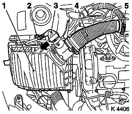
Remove air cleaner housing (1)
| • |
Remove wiring harness plug for hot film mass air flow meter
(3)
| – |
Release in direction of arrow
|
|
| • |
Remove air intake hose (4)
|
|
|
|
| 4. |
Detach front right wheel
|
| 6. |
Remove front right wheel
|
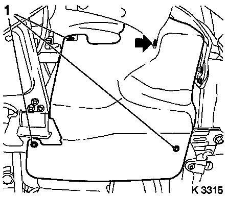
| 8. |
Remove ribbed V-belt cover
|
|
|
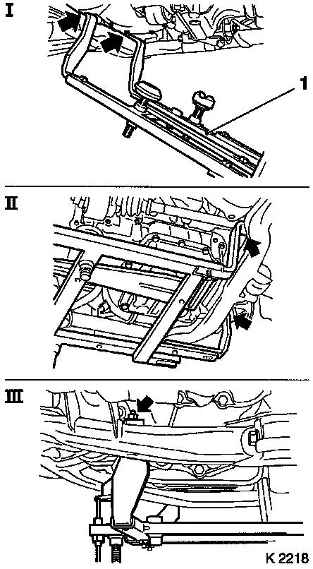
| 9. |
Attach KM-6169 (1)
| • |
Attach KM-6169 at left side of front
axle unit (arrows, fig.I)
Note: Guide pin must be
seated in bore in front axle body
|
| • |
Attach both right holders on the front axle body (arrows,
Illus. II).
Note: Guide pin must be
seated in bore in front axle body (arrow, Fig. III)
|
|
|
|
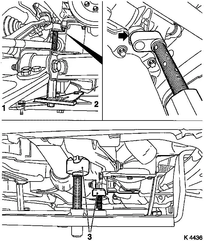
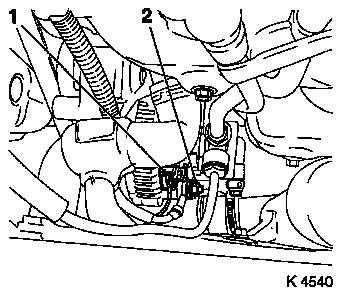
| 10. |
Install support
| • |
Adjust bracket (2) for support
|
|
| 11. |
Adjust supports
| • |
Transmission side
Note: Turn spindles
until mounts (3) are positioned at guide journals free of play
|
| • |
Engine timing side
| – |
Insert journal of the support in the bore of the cylinder block
without play (arrow)
|
|
|
|
|
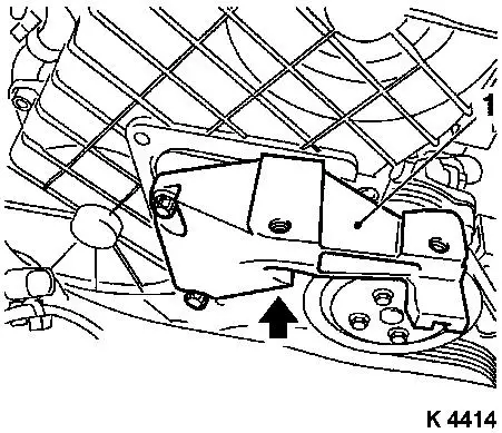
| 13. |
Remove right engine damping block
|
|

|
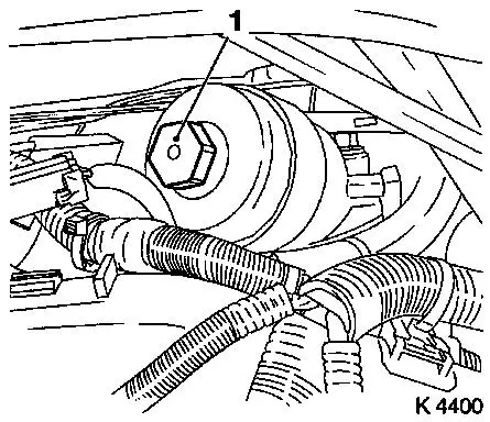
| 14. |
Detach alternator wiring harness
| • |
Disconnect wiring harness plug (1)
|
|
|
|
| 15. |
Remove vacuum pump vacuum lines
| • |
Exhaust gas recirculation solenoid valve
|
|
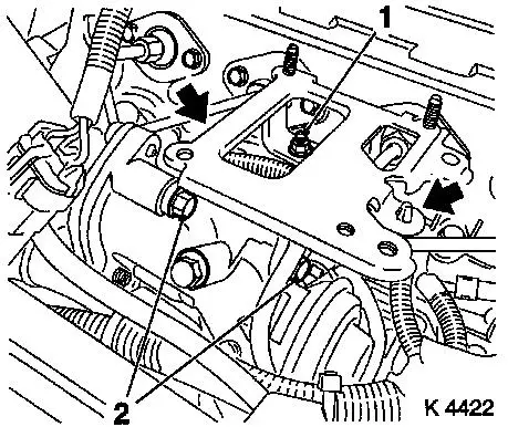
| 16. |
Remove wiring trough
| • |
Unclip vacuum lines (2)
|
| • |
Unclip wiring trough (1)
|
|
|
|
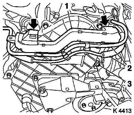
| 17. |
Loosen upper part of toothed belt cover
| • |
Remove 8 bolts
Note: Note dissimilar
bolt lengths
|
|
|
|
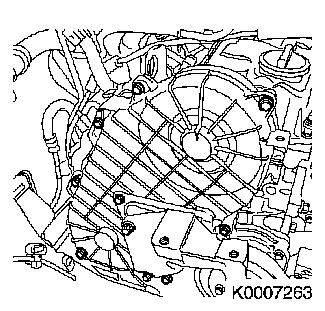
| 18. |
Detach right engine bracket
| • |
Remove right engine bracket, right engine bracket adapter,
upper part of toothed belt cover
|
|
|
|
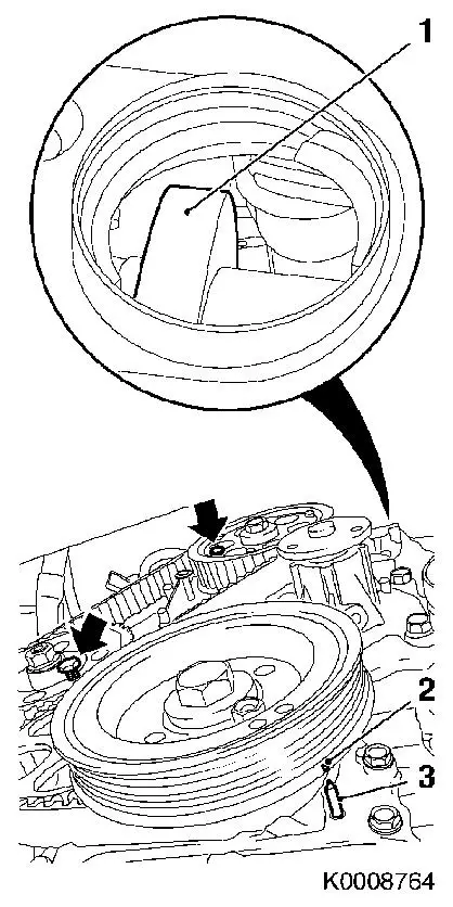
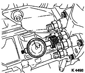
| 19. |
Set no.1 cylinder to TDC
| • |
Rotate crankshaft evenly until torsional vibration damper (2)
mark is flush with pin (3) on oil pump cover. No.1 cylinder exhaust
camshaft (1) must be on top.
|
| • |
Screw in the TDC fixing bolts (arrows)
| – |
Drive gear injection pumps (M8)
|
|
| • |
Unscrew TDC-fixing bolts
|
|
|
|
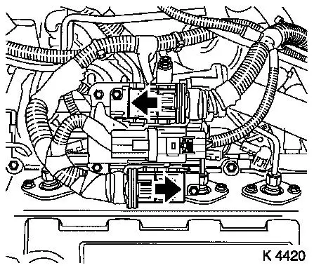
| 20. |
Remove wiring harness plug for engine control unit
| • |
3 off
| – |
Release 2 wiring harness plugs in direction of arrow
|
|
|
|
|
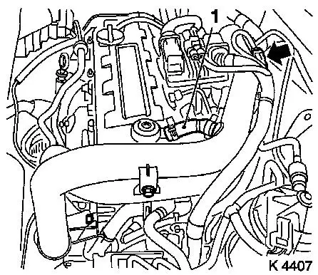
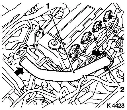
| 21. |
Remove air intake pipe
| • |
Remove vent hose (1)
| – |
From cylinder head cover
|
|
| • |
Unclip wiring harness (arrow)
|
|
|
|
| 22. |
Remove charge air hose
| • |
From turbocharger, centre charge air pipe
|
|
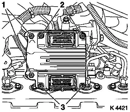
| 23. |
Remove engine control unit
| • |
Unclip wiring harness for engine management
|
| • |
Remove wiring harness plug bracket
|
| • |
Unscrew 2 bolts (2), 2 nuts (3)
|
|
|
|
| 24. |
Remove engine control unit bracket
| • |
Unscrew 2 bolts (2), nut (1)
|
| • |
Unclip wiring harness (arrows)
|
|
|
|
| 25. |
Detach starter/alternator wiring harness bracket
| • |
From exhaust recirculation valve
|
|
| 26. |
Remove centre charge air pipe (1)
| • |
Unscrew studs (2), 2 bolts (arrows)
|
|
|
|
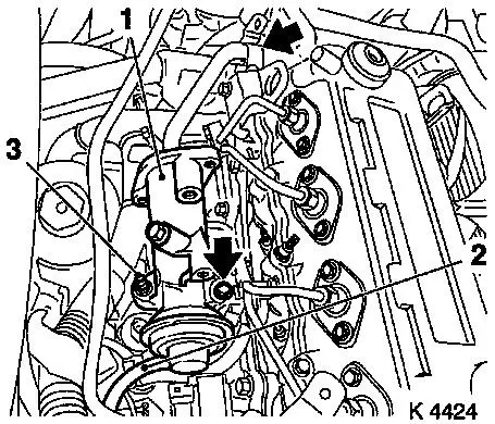
| 27. |
Remove exhaust recirculation valve (1)
| • |
Remove exhaust recirculation pipe
|
| • |
Unscrew studs (3), 2 bolts (arrows)
|
|
|
|
| 28. |
Remove oil filter insert
| • |
Place collecting basin underneath.
|
| • |
Unscrew oil filter housing cover (1)
|
|
|
|
| 29. |
Detach oil filter housing cover return hose
| • |
From oil filter housing
|
|
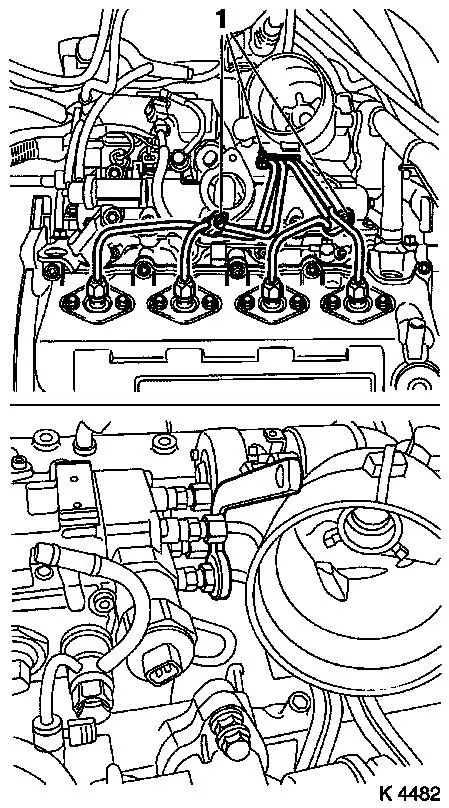
| 30. |
Detach injection line spacers (1)
Note: Mark spacer
positions
|
| 31. |
Remove injection lines
|
|
|
| 32. |
Attach KM-798
| • |
Turn crankshaft in direction of engine rotation to 45°
before no.1 cylinder TDC
| – |
At toothed belt drive gear bolt
|
|
| • |
Remove central bleeder screw
|
| • |
Install KM-798 under pre-tension
|
| • |
Determine BDC position of injection pump plunger by turning
crankshaft back and forth
Note: Dial gauge needle
must not move
|
|
|
|
| 33. |
Check start of feed
| • |
Turn crankshaft to 1st Cylinder TDC
Note: Mark on oil pump
cover must align with mark on torsional vibration damper.
|
Important: If test value is not
achieved, diesel injection pump setting must be corrected - see
operation "Adjusting diesel fuel injection pump".
|
| • |
Read test value
| – |
Test value: 0.28 – 0.38 mm
|
|
|
| 34. |
Remove KM-798
| • |
Tighten central bleeder screw ( 23.5
Nm )
|
|
| 35. |
Install injection lines
| • |
Caution! Injection lines must be installed without tension.
Hand-tighten at injector nozzles and injection pump.
|
| • |
Tighten union nuts ( 22.5 Nm
)
|
|
| 36. |
Install injection line spacers
Note: Pay attention to
spacer positions
|
| 37. |
Attach oil filter housing return hose
|
| 38. |
Install oil filter insert
| • |
Tighten oil filter housing cover ( 23.5
Nm )
|
|
| 39. |
Install exhaust recirculation valve
| • |
Clean sealing surfaces.
|
| • |
Insert exhaust recirculation valve
| – |
Tighten studs, 2 bolts ( 24.5 Nm
)
|
|
| • |
Attach exhaust gas recirculation pipe
| – |
Tighten 2 bolts ( 28.4 Nm )
|
|
|
| 40. |
Install centre charge air pipe
|
| 41. |
Attach starter/alternator wiring harness bracket
|
| 42. |
Install engine control unit bracket
|
| 43. |
Install engine control unit
| • |
Install engine control unit
| – |
Tighten 2 bolts, 2 nuts ( 5.9 Nm
.)
|
|
| • |
Install wiring harness plug bracket
|
|
| 44. |
Install air intake pipe
| • |
Attach engine vent hose
|
|
| 45. |
Attach charge air hose.
|
| 46. |
Connect wiring harness plug for engine control unit
| • |
Connect wiring harness plug.
|
|
| 47. |
Attach right engine bracket
| • |
Insert lower bolt
| – |
Into right engine bracket and right engine bracket adapter
|
|
| • |
Insert right engine bracket, right engine bracket adapter,
upper part of toothed belt cover
|
| • |
Tighten 3 bolts( 40 Nm )
|
|
| 48. |
Fasten upper part of toothed belt cover
| • |
Tighten bolts ( 9.8 Nm )
Note: Note dissimilar
bolt lengths
|
|
| 49. |
Install right engine damping block
| • |
To side member
| – |
Tighten bolts ( 40 Nm )
|
|
| • |
On engine bracket
| – |
Tighten bolts ( 60 Nm + 30° +
15° )
|
|
|
| 51. |
Attach alternator wiring harness
| • |
Connect wiring harness plug.
|
|
| 52. |
Attach vacuum pump vacuum lines
| • |
Route lines and clip in
|
| • |
Tighten union nut ( 18 Nm )
|
|
| 53. |
Install air cleaner housing
| • |
Fasten air intake hose.
|
| • |
Connect wiring harness plug to hot film mass air flow meter
|
|
| 57. |
Install ribbed V-belt cover
|
| 59. |
Install right front wheel
|
| 61. |
Fasten right front wheel
| • |
Tighten bolts ( 110 Nm )
|
|
| 62. |
Check and correct engine oil level
| • |
Observe specified engine oil quantity
|
| • |
Start engine and allow to run until oil pressure telltale
extinguishes.
|
| • |
Check engine oil level, if necessary correct.
|
|
| 64. |
Calibrate steering angle sensor
| • |
Switch on ignition
Note: Rotate the
steering wheel one time from its right-hand to its left-hand
stop.
|
|
| 65. |
Program volatile memories
|
|
