
Ignition switch
- Make
- Alfa Romeo
- Model
- 147 Factory Service Manual
- Year
- 2000–2004
- Section
- Engine starting › Ignition switch
Ignition switch
COMPOSITION
The diagram below illustrates the ignition switch.
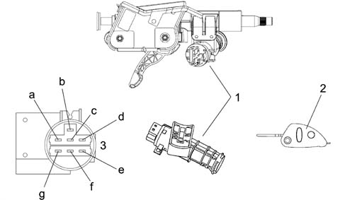
1 - Ignition switch
2 - Ignition key
3 - Electrical connector
a - INT
b - INT/A
c - POS
d - PARK
e - 50
f - 30
g - 15/54
OPERATION
The diagram illustrates the connections.
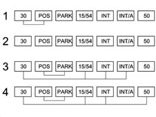
1 - PARK: key can be removed from STOP to PARK by pressing the inhibitor button
2- STOP: key can be removed
3 - DRIVE: key cannot be removed
4 - STARTING: key cannot be removed automatic return to 'DRIVE position
The ignition key with a steering lock is a component which carries out the main function, through the insertion of a coded mechanical key, of supplying several circuits including the ignition/injection system, the engine starting and the services controlled by the ignition.
The steering lock function is included amongst its tasks.
The ignition key is equipped with an 'anti-repeater' device which prevents the starting manoueuvre if the key is not returned to the STOP position.
The steering lock has two safety devices so that if one of them is broken and the ignition key is in the ON position the steering column cannot be mechanically locked.
If the parking lights button is pressed it is possible to move from STOP to PARK and it is automatically released by turning the key to the STOP position.
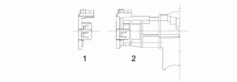
1 - Aerial for ALFA CODE
2 - Aerial fitted on the switch
The ignition switch is also used as a support for the aerial needed in transferring the codes in the ignition key transponder and is used by the ALFA CODE system for releasing the injection control unit (NCM) and allowing the engine to be started up.
The diagram below illustrates the switch electrical connections.
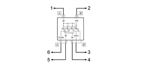
1 - To pin D maxifuse F73-30A control unit on battery
2 - To pin 2 connector PM dashboard control unit
3 - To pin 1 connector PM dashboard control unit
4 - To pin 11 connector PM dashboard control unit
5 - To pin 15 connector AA engine compartment/Selespeed starting relay
6 - To pin 30 connector AA engine compartment control unit
Parts & tools for this job For 2000 Alfa Romeo 147
- TOOLOBD2 scannerSearch: OBD2 scanner
- TOOLDigital multimeterSearch: automotive digital multimeter
- TOOLBack-probe test leadsSearch: back probe test leads
Links open Amazon search results in a new tab. As an Amazon Associate I earn from qualifying purchases.