
Engind front cover - r r
- Make
- Alfa Romeo
- Model
- 147 Factory Service Manual
- Year
- 2000–2004
- Section
- Crankcase sump and covers › Engind front cover - r r
Engind front cover - r r
Removing
1. Fit the tool.
| Name | Country | |
|---|---|---|
| 1 | Counter-torque | 1.820.624.000 |
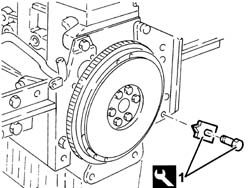
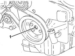
1. Slacken the bolt securing the timing belt pulley.
Remove the tool.
| Name | Country | |
|---|---|---|
| Counter-torque | 1.820.624.000 |
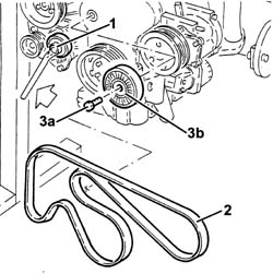
1. Adjust the automatic belt tensioner with a wrench to slacken the tension of the single drive belt.
2. Remove the single drive belt.
3. Undo the bolt (3a) and rmeove the fixed belt tensioner (3b) for the engine components single belt.
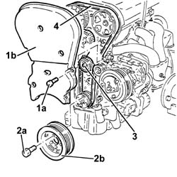
1. Undo the bolts (1a) and remove the upper timing belt guard (1b).
2. Undo the bolts (2a) and remove the engine components belt drive pulley (2b).
3. Loosen the timing belt tensioner nut.
4. Remove the timing belt.
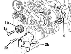
1. Completely undo the bolt (1a) loosened previously and remove the timing drive belt pulley (1b).
2. Undo the bolts (2a) and remove the timing side rigid power unit support (2b).
3. Disconnect the connector on the water outlet pipe from the water-oil heat exchanger.
4. Disconnect the water inlet pipe to the water-oil heat exchanger.
Rotate the engine through 180° on the overhauling stand.
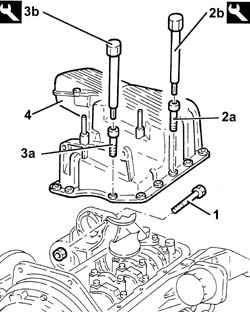
1. Undo the bolt connecting the oil sump to the intermediate shaft support.
2. Undo the front and rear bolts (2a) for the crankcase sump using the tool (2b).
| Name | Country | |
|---|---|---|
| 2b | Key | 1.822.145.000 |
3. Undo the side bolts (3a) for the crankcase sump using the tool (3b).
| Name | Country | |
|---|---|---|
| 3b | Key | 1.822.144.000 |
4. Remove the crankcase sump.
To release the sump, tap it gently with a wooden or resin hammer, then use a screwdriver to lever against the specific projections on the sides of the sump.
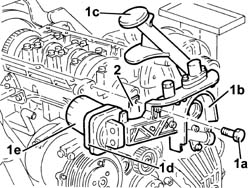
1. Undo the bolts (1a) and remove the oil pump (1b) complete with intake duct (1c), water-oil heat exchanger (1d) and oil filter (1e).
2. Remove the gasket.
Remove the crankshaft front oil seal.
Refitting
Fit the oil pump complete with intake duct, water-oil heat exchanger, oil filter and a new gasket and tighten the bolts to the recommended torque.
| Fastening | Component | Ø | Value (daNm) |
|---|
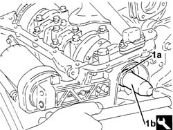
1. Fit a new crankshaft front oil seal (1a) using the tool (1b).
| Name | Country | |
|---|---|---|
| 1b | Fitting tool | 1.821.247.000 |
Apply silicon sealant around the edge of the crankcase sump.
Fit the crankcase sump.
Tighten the front and rear bolts for the crankcase sump to torque using the tool.
| Fastening | Component | Ø | Value (daNm) |
|---|
| Name | Country | |
|---|---|---|
| Key | 1.822.145.000 |
Tighten the side bolts for the crankcase sump to torque using the tool.
| Fastening | Component | Ø | Value (daNm) |
|---|
| Name | Country | |
|---|---|---|
| Key | 1.822.144.000 |
Tighten the bolt securing the oil sump to the intermediate shaft support.
Rotate the engine through 180° on the overhauling stand.
Connect the water inlet pipe to the water-oil heat exchanger and fix it using the clip.
Tighten the connector on the water outlet pipe from the water-oil heat exchanger.
Fit the power unit support, timing gear side, and fix it using the bolts.
Fit the timing belt drive pulley and fix it using the bolt, without tightening it.
1. Disconnect the electrical connections from the ignition coils.
| Name | Connector | |
|---|---|---|
| 1 | Ignition coil | A30 |
2. Disconnect the earth lead from the cylinder head.
3. Disconnect the high-tension leads (3a) from the spark plugs using the tool (3b).
| Name | Country | |
|---|---|---|
| 3b | Pliers | 1.820.636.000 |
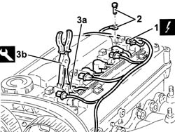
Undo the bolts and remove the bracket complete with ignition coils and high-tension leads.
Undo the bolts and remove the rocker cover complete with gasket.
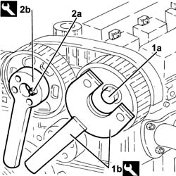
1. Slacken the bolt (1a) on the exhaust side camshaft pulley, using the tools (1b) for counter-torque.
| Name | Country | |
|---|---|---|
| 1b | Counter-torque | 1.822.146.000 |
| Name | Country | |
|---|---|---|
| 1b | Counter-torque | 1.822.156.000 |
2. Slacken the bolts (2a) on the inlet side camshaft pulley, using the tool (2b) for counter-torque.
| Name | Country | |
|---|---|---|
| 2b | Counter-torque | 1.822.155.000 |
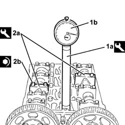
1. Fit the tool (1a), complete with dial gauge (1b), in the housing of the spark plug for cylinder no. 1.
| Name | Country | |
|---|---|---|
| 1a | Extension | 1.825.013.000 |
Rotate the crankshaft until the piston for cylinder no. 1 is at T.D.C. at the power stroke.
Undo the bolts an remove the third caps from the inlet and exhaust camshafts.
2. Fit the tool (2a) in place of the removed camshaft caps, and fix it tightening the bolts (2b) to the recommended torque.
Check that the camshaft cam profile matches the tool perfectly.
| Name | Country | |
|---|---|---|
| 2a | Gauge | 1.870.797.000 |
| Fastening | Component | Ø | Value (daNm) | |
|---|---|---|---|---|
| 2b | Bolt | ENGINE TIMING ADJUSTMENT TEMPLATES | M7 | (Cylinder head side) 1.0 |
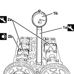
1. Fit the tool (1a), complete with dial gauge (1b), in the housing of the spark plug for cylinder no. 1.
| Name | Country | |
|---|---|---|
| 1a | Extension | 1.825.013.000 |
Rotate the crankshaft until the piston for cylinder no. 1 is at T.D.C. at the power stroke.
Undo the bolts an remove the third caps from the inlet and exhaust camshafts.
2. Fit the tool (2a) in place of the removed camshaft caps, and fix it tightening the bolts (2b) to the recommended torque.
Check that the camshaft cam profile matches the tool perfectly.
| Name | Country | |
|---|---|---|
| 2a | Gauge | 1.870.734.000 |
| Fastening | Component | Ø | Value (daNm) | |
|---|---|---|---|---|
| 2b | Bolt | ENGINE TIMING ADJUSTMENT TEMPLATES | M7 | (Cylinder head side) 1.0 |
Fit the timing belt.
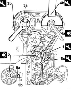
1. Apply maximum tension to the timing belt using the tool.
| Name | Country | |
|---|---|---|
| 1 | Key | 1.822.149.000 |
2. Tighten the belt tensioner nut to the recommended torque.
| Fastening | Component | Ø | Value (daNm) | |
|---|---|---|---|---|
| 2 |
3. Tighten the bolts (3a) for the inlet side camshaft pulley to the recommended torque, using the tool (3b) for counter-torque.
| Fastening | Component | Ø | Value (daNm) | |
|---|---|---|---|---|
| 3a |
| Name | Country | |
|---|---|---|
| 3b | Counter-torque | 1.822.155.000 |
4. Tighten to torque the bolt (4a) on the exhaust side camshaft pulley, using the tools (4b) for counter-torque.
| Fastening | Component | Ø | Value (daNm) | |
|---|---|---|---|---|
| 4a |
| Name | Country | |
|---|---|---|
| 4b | Counter-torque | 1.822.146.000 |
| Name | Country | |
|---|---|---|
| 4b | Counter-torque | 1.822.156.000 |
Undo the bolts and remove the tool.
| Name | Country | |
|---|---|---|
| Gauge | 1.870.797.000 |
Undo the bolts and remove the tool.
| Name | Country | |
|---|---|---|
| Gauge | 1.870.734.000 |
Fit the camshaft caps removed previously and tighten the bolts to torque.
| Fastening | Component | Ø | Value (daNm) |
|---|
Rotate the crankshaft through two revolutions.
Slacken the timing belt tensioner nut.
5. Line up the moving reference (5a) on the timing belt tensioner with the reference hole (5b) using the tool (5c).
| Name | Country | |
|---|---|---|
| 5c | Key | 1.822.149.000 |
Tighten the timing belt tensioner nut to the specified torque.
| Fastening | Component | Ø | Value (daNm) |
|---|
Remove the tool complete with dial gauge.
| Name | Country | |
|---|---|---|
| Extension | 1.825.013.000 |
Fit the spark plug for cylinder no. 1.
Fit the rocker cover complete with gasket and fix it using the bolts.
Fit the bracket complete with ignition coils and high-tension cables and fix it using the bolts
Connect the high tension leads to the spark plugs.
Connect the earth lead to the cylinder head.
Connect the electrical connections to the ignition coils.
Fit the upper timing belt guard and fix it using the bolts.
Fit the single drive belt pulley and tighten the bolts to torque.
| Fastening | Component | Ø | Value (daNm) |
|---|
Fit the fixed single drive belt tensioner and fix it with its bolt.
Fit the auxiliary components drive belt, using a spanner to lever on the automatic belt tensioner.
Fit the tool.
| Name | Country | |
|---|---|---|
| Counter-torque | 1.820.624.000 |
Tighten the timing belt pulley bolt to the recommended torque.
| Fastening | Component | Ø | Value (daNm) |
|---|
Remove the tool.
| Name | Country | |
|---|---|---|
| Counter-torque | 1.820.624.000 |
Removing
1. Fit the tool.
| Name | Country | |
|---|---|---|
| 1 | Counter-torque | 1.860.161.001 |
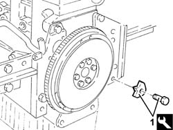
1. Loosen the bolt fixing the camshaft drive pulley.
Remove the tool.
| Name | Country | |
|---|---|---|
| Counter-torque | 1.860.161.001 |
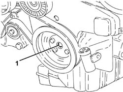
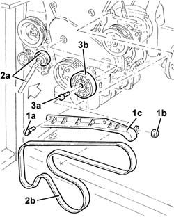
1. Undo the bolts (1a) and the nut (1b) and remove the auxiliary units drive belt protection (1c).
2. Use a spanner on the moving tensioner (2a) and remove the single accessory drive belt (2b).
3. Remove the cap, undo the bolt (3a) and remove the single engine component belt fixed tensioner (3b).
1. Undo the bolts (1a) and remove the upper timing gear covers (1b).
2. Undo the bolts (2a) and remove the engine component drive pulley (2b).
3. Undo the bolt (3a) and remove the lower cam cover (3b).
4. Loosen the nut for the counter-balance shaft toothed drive belt tensioner.
5. Prise off and remove the toothed counter-rotating shaft belt.
6. Slacken the nut on the timing belt moving tensioner.
7. Prise off and remove the timing belt.
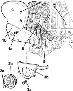
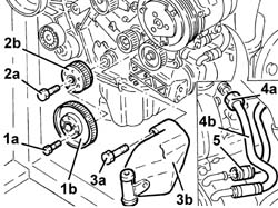
1. Undo the bolts (1a) and remove the counter-balance shaft drive belt drive pulley (1b).
2. Fully undo the bolt (2a) previously slackened and remove the toothed timing belt drive pulley (2b).
3. Undo the bolts (3a) and remove the timing side rigid power unit support (3b).
4. Undo the connector (4a) for the coolant outlet pipe from the engine oil heat exchanger on the side of the water pump rigid inlet pipe.
5. Disconnect the coolant inlet sleeve to the engine oil heat exchanger, exchanger side.
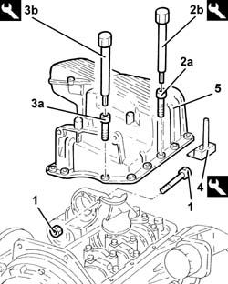
Rotate the engine through 180° on the overhauling stand.
1. Undo the bolt fixing the crankcase sump to the support on the engine for the reaction rod.
2. Undo the front and rear bolts (2a) for the crankcase sump using the tool (2b).
| Name | Country | |
|---|---|---|
| 2b | Key | 1.822.145.000 |
3. Undo the side bolts (3a) for the crankcase sump using the tool (3b).
| Name | Country | |
|---|---|---|
| 3b | Key | 1.822.144.000 |
4. Cut the crankcase sump sealant using the tool.
| Name | Country | |
|---|---|---|
| 4 | Blade | 1.870.718.000 |
5. Remove the crankcase sump.
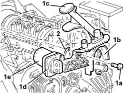
1. Undo the bolts (1a) and remove the crankshaft front cover (1b) complete with inlet (1c), engine oil heat exchanger (1d) and engine oil filter (1e).
2. Remove the seal.
Prise up and remove the crankshaft front oil seal.
Take care not to damage the oil seal seat during removal.
Refitting
Place the crankshaft front cover, complete with intake, engine oil heat exchanger, oil filter and a new gasket, back in its housing, then secure it tightening the bolts to the recommended torque.
| Fastening | Component | Ø | Value (daNm) | |
|---|---|---|---|---|
| Bolt | CRANKSHAFT FRONT COVER | M6 | (Engine crankcase side) 0.8 ÷ 1.0 |
1. Refit a new front crankshaft front cover oil seal (1a) using tool (1b).
| Name | Country | |
|---|---|---|
| 1b | Fitting tool | 1.821.247.000 |
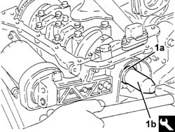
Clean the matching surfaces of crankcase sump and cylinder block.
Apply silicone sealant around the edge of the crankcase sump.
1. Place the crankcase sump back in its housing.
2. Tighten the front and rear bolts (2a) fixing the crankcase sump to the recommended torque using the tool (2b).
| Fastening | Component | Ø | Value (daNm) | |
|---|---|---|---|---|
| 2a | Bolt | OIL SUMP | M8 | (Engine crankcase side) 2.3 ÷ 2.8 |
| Name | Country | |
|---|---|---|
| 2b | Key | 1.822.145.000 |
3. Tighten the side bolts (3a) for the crankcase sump to the recommended torque using the tool (3b).
| Fastening | Component | Ø | Value (daNm) | |
|---|---|---|---|---|
| 3a | Bolt | OIL SUMP | M6 | (Engine crankcase side) 0.8 ÷ 1.0 |
| Name | Country | |
|---|---|---|
| 3b | Key | 1.822.144.000 |
4. Tighten the bolt securing the oil sump to the intermediate shaft support.
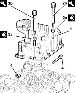
Rotate the engine through 180° on the overhauling stand.
Connect the coolant inlet sleeve to the engine oil heat exchanger, exchanger side.
Connect the engine oil heat exchanger coolant outlet pipe, rigid fluid inlet pipe side, to the water pump and tighten the connector.
Fit the timing side power unit rigid rear support and fix it tightening the bolts to the recommended torque.
| Fastening | Component | Ø | Value (daNm) | |
|---|---|---|---|---|
| Bolt | ENGINE MOUNT TIMING SIDE | M10 | (Crankcase side) 4.5 ÷ 5.5 |
Place the drive pulley back in its housing and secure it tightening the bolt to the recommended torque.
Disconnect the electrical connection for the air conditioner compressor.
| Name | Connector | |
|---|---|---|
| Air conditioning compressor engagement electro-magnet | L20 |
1. Disconnect the electrical connections from the ignition coils and release the wiring from the fixings.
| Name | Connector | |
|---|---|---|
| 1 | Ignition coil | A30 |
2. Undo the bolt (2a) and disconnect the earth lead (2b) from the ignition coils single support plate.
| Name | Connector | |
|---|---|---|
| 2b | Earth on engine | C40B |
3. Disconnect the caps for the high tension leads (3a) from the spark plugs using the tool (3b).
| Name | Country | |
|---|---|---|
| 3b | Pliers | 1.820.636.000 |
4. Disconnect the oil vapour recovery pipe from the rocker cover.
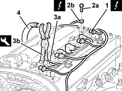
Undo the bolts fixing the ignition coil support plate.
Pull up the plate complete with ignition coils.
Undo the bolts and remove the rocker cover complete with gasket.
1. Loosen the bolt (1a) for the exhaust side timing driven pulley using tools (1b) and (1c) for counter-torque.
| Name | Country | |
|---|---|---|
| 1b | Counter-torque | 1.822.146.000 |
| Name | Country | |
|---|---|---|
| 1c | Counter-torque | 1.822.156.000 |
2. Loosen the bolts (2a) for the inlet side camshaft driven pulley using tool (2b) for counter-torque.
| Name | Country | |
|---|---|---|
| 2b | Counter-torque | 1.822.155.000 |
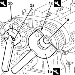
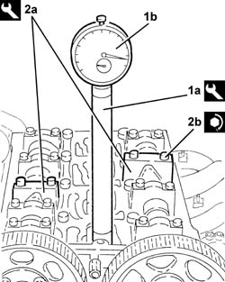
1. Fit the tool (1a), complete with dial gauge (1b), in the housing of the spark plug for cylinder no. 1.
| Name | Country | |
|---|---|---|
| 1a | Extension | 1.825.013.000 |
Rotate the crankshaft until the piston for cylinder no. 1 is at T.D.C. at the combustion stroke.
If TDC is exceeded, do not turn backwards, but proceed by rotating the crankshaft through a further two revolutions in the same direction until the piston for cylinder no. 1 is at TDC.
Undo the bolts and remove the camshaft third cap.
2. Fit the tool (2a) in place of the removed camshaft caps, and fix it tightening the bolts (2b) to the specified torque.
Check that the camshaft cam profile matches the tool correctly.
| Name | Country | |
|---|---|---|
| 2a | Gauge | 1.825.041.000 |
| Fastening | Component | Ø | Value (daNm) | |
|---|---|---|---|---|
| 2b | Bolt | ENGINE TIMING ADJUSTMENT TEMPLATES | M7 | (Cylinder head side) 1.0 |
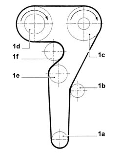
1. Fit the toothed timing belt following the order shown in the diagram:
toothed drive pulley (1a)
fixed tensioner (1b)
exhaust side toothed driven pulley (1c)
Before fitting the belt on the exhaust side driven pulley, rotate it in a clockwise direction (see diagram) until the end of travel position.
intake side toothed driven pulley (1d)
Before fitting the belt on the inlet side driven pulley, rotate it in a clockwise direction (see diagram) until the end of travel position.
mobile tensioner (1e)
coolant pump pulley (1f).
When fitting, ensure that the arrow stamped on the belt is facing in the direction of engine rotation (clockwise - timing side).
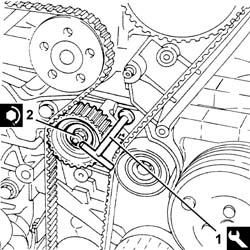
1. Using the tool, rotate the timing moving tensioner until the maximum tension is applied to the timing belt.
| Name | Country | |
|---|---|---|
| 1 | Key | 1.822.149.000 |
2. Tighten the nut for the moving tensioner to the recommended torque.
| Fastening | Component | Ø | Value (daNm) | |
|---|---|---|---|---|
| 2 | Nut | MOBILE TIMING TENSIONER | M8 | 2.3 ÷ 2.8 |
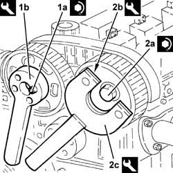
1. Tighten the bolts (1a) for the camshaft driven pulley, inlet side, to the recommended torque using the tool (1b) for counter-torque.
| Fastening | Component | Ø | Value (daNm) | |
|---|---|---|---|---|
| 1a | Bolt | TIMING GEAR DRIVEN PULLEYS | M6 | (Inlet camshaft side) 0.8 ÷ 1.0 |
| Name | Country | |
|---|---|---|
| 1b | Counter-torque | 1.822.155.000 |
2. Tighten the bolt (2a) fixing the timing driven pulley to the recommended torque, using the tools (2b) and (2c) for counter-torque.
| Fastening | Component | Ø | Value (daNm) | |
|---|---|---|---|---|
| 2a | Bolt | TIMING GEAR DRIVEN PULLEYS | M12 | (Exhaust camshaft side) 10.8÷13.2 |
| Name | Country | |
|---|---|---|
| 2b | Counter-torque | 1.822.156.000 |
| Name | Country | |
|---|---|---|
| 2c | Counter-torque | 1.822.146.000 |
Remove the tool for timing the camshafts.
| Name | Country | |
|---|---|---|
| Gauge | 1.825.041.000 |
Place the previously removed camshaft caps back in their housings and secure them tightening the bolts to the recommended torque.
| Fastening | Component | Ø | Value (daNm) | |
|---|---|---|---|---|
| Bolt | CAMSHAFT CAPS | M7 | (Cylinder head side) 1.4 ÷ 1.7 |
Rotate the crankshaft through two revolutions in its direction of rotation (clockwise - timing side) and ensure that the piston for cylinder no. 1 is at TDC.
1. Fit the tool (1a) for keeping the moving timing tensioner still and loosen the tensioner nut (1b).
| Name | Country | |
|---|---|---|
| 1a | Key | 1.822.149.000 |
2. Rotate the tool (2a) in an anti-clockwise direction (timing side) until the tensioner moving reference (2b) coincides with the reference opening (2c).
| Name | Country | |
|---|---|---|
| 2a | Key | 1.822.149.000 |
3. Tighten the nut for the moving tensioner to the recommended torque.
| Fastening | Component | Ø | Value (daNm) | |
|---|---|---|---|---|
| 3 | Nut | MOBILE TIMING TENSIONER | M8 | 2.3 ÷ 2.8 |
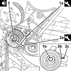
Rotate the crankshaft through two revolutions in its direction of rotation (clockwise - timing side) until cyllinder no. 1 is at TDC in the combustion stroke and check that the engine timing is correct using the tool.
| Name | Country | |
|---|---|---|
| Gauge | 1.825.041.000 |
Remove the tool to check T.D.C. from the cylinder 1 spark plug socket.
| Name | Country | |
|---|---|---|
| Extension | 1.825.013.000 |
Place the spark plugs for cylinder no. 1 back in their housings and tighten them to the recommended torque.
| Fastening | Component | Ø | Value (daNm) | |
|---|---|---|---|---|
| SIDE SPARK PLUG | M10 | (Cylinder head side) 1.0 ÷ 1.3 |
| Fastening | Component | Ø | Value (daNm) | |
|---|---|---|---|---|
| CENTRE SPARK PLUG | M14 | (Cylinder head side) 2.3 ÷ 2.8 |
Place the counter-balance shaft drive belt drive pulley back in its housing and secure it tightening the bolts to the recommended torque.
| Fastening | Component | Ø | Value (daNm) | |
|---|---|---|---|---|
| Bolt | COUNTER-ROTATING SHAFT DRIVE PULLEY | M6 | (Timing drive. pulley. side) 0.8 - 1.0 |
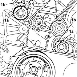
1. Rotate the counter-balance shafts so that the references (1a) on the pullies are aligned with the ribs (1b).
2. Temporarily fit the lower timing cover and the crankshaft pulley and check the alignment of the references.
Fit the counter-balance shaft toothed drive belt.
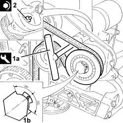
1. Tension the counter-balance shaft drive belt using the tool (1a) so that the reference opening (1b) in the belt tensioner is at the centre of the rotation sector.
| Name | Country | |
|---|---|---|
| 1a | Key | 1.822.154.000 |
2. Tighten the nut fixing the counter-balance shaft drive belt tensioner to the recommended torque.
| Fastening | Component | Ø | Value (daNm) | |
|---|---|---|---|---|
| 2 | Nut | COUNTER-ROTATING SHAFT BELT TENSIONER | M6 | (.Left. counter balance shaft front) cover side 0.8÷1.0 |
Place the tapper cover, complete with gasket, back in its housing and fix it using the bolts.
Place the plate and ignition coil back in its housing and secure it using the bolts.
Connect the oil vapour recovery pipe to the rocker cover.
Connect the high tension lead covers to the spark plugs.
Connect the earth lead to the ignition coils support plate and secure it using the bolt.
Connect the electrical connections to the ignition coils and secure the electrical wiring.
Connect the electrical connection to the air conditioner compressor
Fit the lower protective timing cover and secure using the bolts.
Fit the upper protective timing gear cover and fix it using the bolts.
Fit the engine component drive pulley and fix it tightening the bolts to the recommended torque.
| Fastening | Component | Ø | Value (daNm) | |
|---|---|---|---|---|
| Bolt | CRANKSHAFT PULLEY | M8 | 2.3 ÷ 2.8 |
Place the engine components single drive belt fixed tensioner back in its housing and fix it tightening the bolt to the recommended torque.
| Fastening | Component | Ø | Value (daNm) | |
|---|---|---|---|---|
| Bolt | FIXED SINGLE SERVICE BELT TENSIONER | M8 | 2.3 ÷ 2.8 |
Place the plug back in its housing in the fixed tensioner.
Use a spanner on the moving tensioner and fit the engine components single drive belt.
Place the auxiliary units drive belt protection back in its housing and secure it using the bolts and the nut.
Fit the tool.
| Name | Country | |
|---|---|---|
| Counter-torque | 1.860.161.001 |
Tighten the bolt (left-hand) on the drive pulley to the specified torque.
| Fastening | Component | Ø | Value (daNm) | |
|---|---|---|---|---|
| Bolt with left hand thread | TOOTHED DRIVE PULLEY | M16 | (Crankshaft side) 20.9 ÷ 23.1 |
Remove the tool.
| Name | Country | |
|---|---|---|
| Counter-torque | 1.860.161.001 |
Parts & tools for this job For 2000 Alfa Romeo 147
- PARTEngine gasket setSearch: Alfa Romeo 147 2000 engine gasket set
- TOOLTorque wrenchSearch: 3/8 inch torque wrench
- TOOLFeeler gauge setSearch: feeler gauge set
Links open Amazon search results in a new tab. As an Amazon Associate I earn from qualifying purchases.