
E5020 Engine cooling
- Make
- Alfa Romeo
- Model
- 147 Factory Service Manual
- Year
- 2000–2002
- Section
- Engine command and control systems › E5020 Engine cooling
E5020 Engine cooling
Description
The engine radiator and air conditioner condenser cooling system consists of one fan operated at two different speeds.
- the first speed is activated at a first coolant temperature level or at a certain air conditioner coolant pressure.
- the second speed cuts in at a higher temperature or pressure threshold.
The fan is operated by two specific relays located in the engine compartment unit.
The fan supply line is protected by two specific fuses, located in the engine compartment unit.
The fan can only be switched on when the ignition is ON.
Description of operation
The relays T6 and T7 in the engine compartment unit B1 manage the switching on of the fan N11 at two speeds: their coils are supplied by the ignition-controlled line (15/54), while the power lines are protected by the fuses F6 and F7, of the engine compartment unit B1.
Both are energized by a control signal - earth - coming from the engine control unit M10.
If the engine coolant reaches a first temperature level, or the 4-stage pressure switch K10 indicates to the control unit M10 - pin 9 of connector A - that a first pressure level has been reached, the control unit M10 sends a signal - from pin 50 of connector A - to the fan 1st speed relay, which then sends the supply to the fan N11 via the additional resistor O10: the fan thus turns at the first speed (slow).
If the coolant reaches a higher temperature level, or the 4-stage pressure switch K10 indicates to the control unit M10 - pin 41 of connector A - that a higher pressure has been reached, the control unit M10 sends a signal - from pin 62 of connector A - to the fan 2nd speed relay T7, which sends the supply directly to the fan N11: the fan then turns at the maximum speed.
Wiring diagram
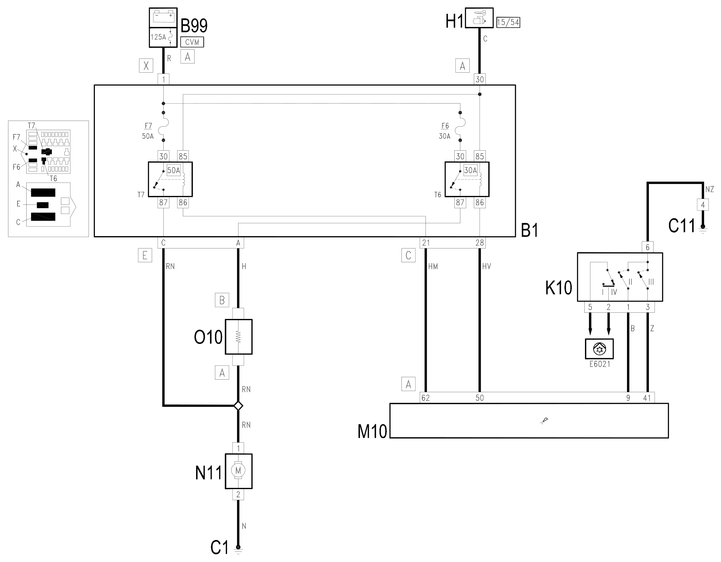
Components
| Code | Component | See |
|---|---|---|
| B01 | Engine compartment junction unit | description 5505A |
| B99 | Maxifuse box on battery | description 5530B |
| C01 | Battery earth | |
| C11 | Right front earth | |
| H01 | Ignition switch | description 5520A |
| K10 | 4 stage pressure switch | description 5540B |
| M10 | Engine management ECU | description 1056B |
| N11 | Engine electric fan motor | description 1088E |
| O10 | Engine fan adjustment resistor | description 1088E |
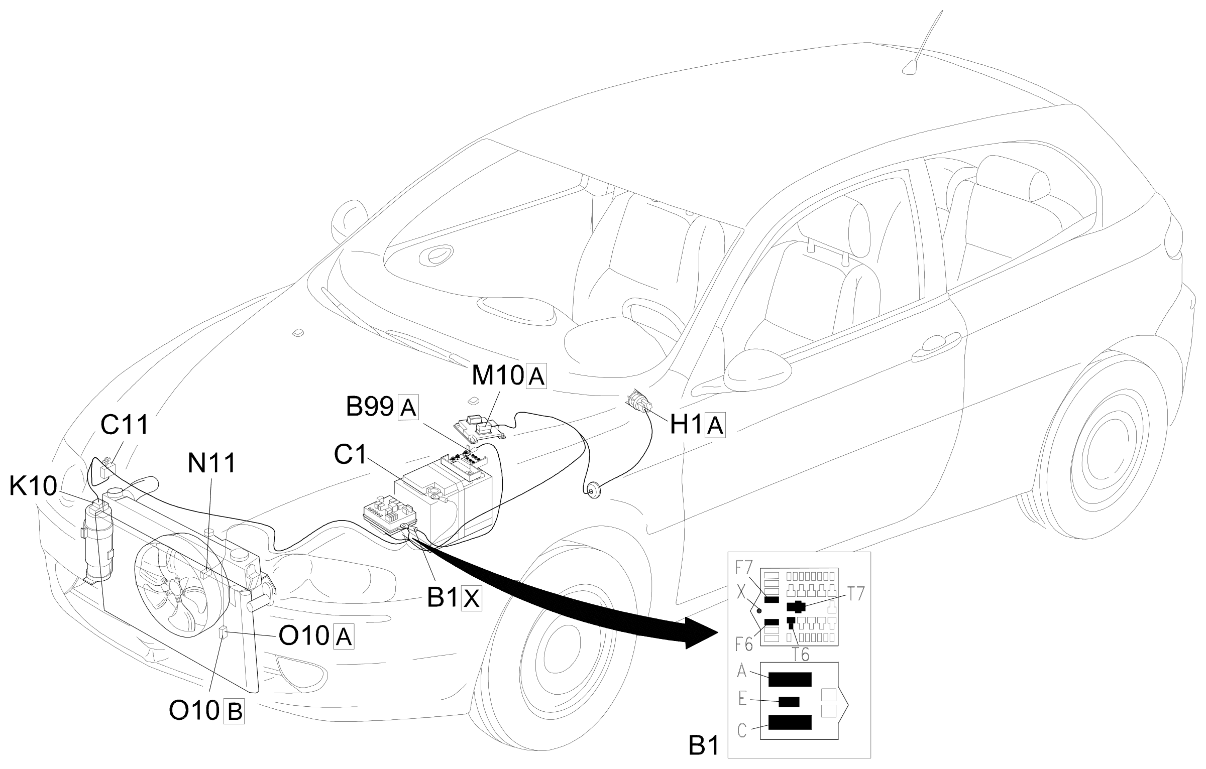
Component location
Parts & tools for this job For 2000 Alfa Romeo 147
- PARTEngine gasket setSearch: Alfa Romeo 147 2000 engine gasket set
- TOOLTorque wrenchSearch: 3/8 inch torque wrench
- TOOLFeeler gauge setSearch: feeler gauge set
Links open Amazon search results in a new tab. As an Amazon Associate I earn from qualifying purchases.