
Engine bay control unit
- Make
- Alfa Romeo
- Model
- 147 Factory Service Manual
- Year
- 2000–2002
- Section
- Instrument/guage electrical wiring › Engine bay control unit
ENGINE BAY CONTROL UNIT
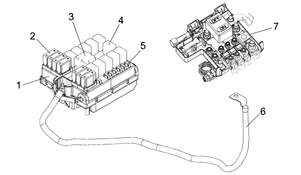
- 1 Engine bay control unit (CVM)
- 2 System protection maxifuse
- 3 Maxi type relay
- 4 Micro type relay
- 5 System protection mini fuse
- 6 Connection cable between battery control unit (CBA) and engine bay control unit (CVM)
- 7 Battery control unit (CBA)
Electromechanical control unit including fuses (maxi and mini), relays and circuits for interconnecting front wiring and radiator prewiring.
These wires are connected to the control unit via fixed joints. All fixed joints must be easily accessible and arranged in such a way as to facilitate assembly. A tray beneath the protectivecover houses any further connectors/relays/fuses
A fastening is provided on the lower cover for sealed fuse carrier connectors (maxi and mini type).
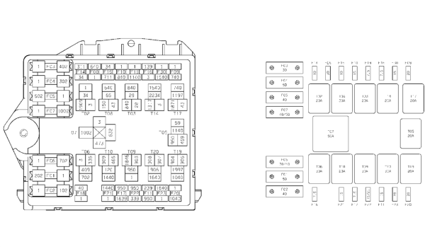
The maxi fuses grouped on the battery control unit (CBA) and engine bay control unit (CVM) are connected directly to the battery positive terminal and protect the main power supply lines.
The engine bay control unit (CVM) is described below
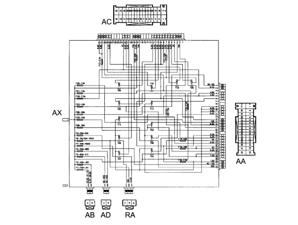
In the more comprehensive version, the engine bay control unit protects the electrical equipment by means of the following fuses:
| COD | COMPONENT | In | TYPE |
|---|---|---|---|
| F-1 | FUSE GLOW PLUG PREHEATING | 50 | MAXI |
| F-2 | FUSE FACIA CONTROL UNIT 2 | 40 | MAXI |
| F-3 | FUSE IGNITION SWITCH | 20 | MAXI |
| F-4 | FUSE BRAKE NODE (NFR) | 50 | MAXI |
| F-5 | FUSE SOLENOID CLIMATE CONTROL SYSTEM | 40 | MAXI |
| F-6 | FUSE RADIATOR FAN 1 | 30Bz / 40Ds | MAXI |
| F-7 | FUSE RADIATOR FAN 2 | 50Bz / 60Ds | MAXI |
| F-8 | FUSE HEATING SUPPLEMENTARY (PTC 1) | 30 | mini |
| F-9 | FUSE HEADLAMP WASHER | 20 | mini |
| F-10 | FUSE HORNS | 15 | mini |
| F-11 | FUSE I.E. SECONDARY SERVICES | 15 | mini |
| F-14 | FUSE RIGHT HEADLAMP | 10 | mini |
| F-15 | FUSE LEFT MAIN BEAM | 10 | mini |
| F-16 | FUSE 15/54 I.E. SYSTEM | 7.5 | mini |
| F-17 | FUSE I.E. PRIMARY SERVICES | 7.5 | mini |
| F-18 | FUSE +30 I.E. CONTROL UNIT | 7.5 | mini |
| F-19 | FUSE COMPRESSOR | 7.5 | mini |
| F-20 | FUSE HEATED DIESEL FILTER | 20 | mini |
| F-21 | FUSE FUEL PUMP | 15 | mini |
| F-22 | FUSE IGNITION COILS/ INJECTORS | 15 Bz / 20 Ds | mini |
| F-23 | FUSE FOR RELAY T20 (predisposition) | mini | |
| F-30 | FUSE FOG LIGHTS | 15 | mini |
The following relays are present in the engine bay control unit:
| CODE | COMPONENT | In | TYPE |
|---|---|---|---|
| T03 | 20 | micro | |
| T05 | 20 | micro | |
| T06 | 30 | micro | |
| T07 | 50 | MAXI | |
| T08 | 30 | micro | |
| T09 | 30 | micro | |
| T10 | 20 | micro | |
| T14 | 20 | micro | |
| T17 | 20 | micro | |
| T19 | 20 | micro | |
| T20 | micro |
Wiring diagram of engine bay control unit interior (CVM)
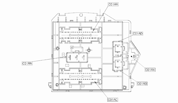
- C01RA 3 PIN connector
- C01AA 23 pin connector
- C01AD 2 PIN connector
- C01AB 2 PIN connector
- C01AC 32 PIN connector
- C01AX 1 PIN connector (on the front part)
Rear view
Parts & tools for this job For 2000 Alfa Romeo 147
- PARTEngine gasket setSearch: Alfa Romeo 147 2000 engine gasket set
- TOOLTorque wrenchSearch: 3/8 inch torque wrench
- TOOLFeeler gauge setSearch: feeler gauge set
Links open Amazon search results in a new tab. As an Amazon Associate I earn from qualifying purchases.