
Venice plus system structure
- Make
- Alfa Romeo
- Model
- 147 Factory Service Manual
- Year
- 2000–2002
- Section
- Instrument/guage electrical wiring › Venice plus system structure
‹ Prev Ve.n.i.ce (vehicle network integration component electronics) architectureNext › Operation of the multiplex network (ve.n.i.ce plus system)
Electrical equipmentVenice plus system structure
VENICE PLUS SYSTEM STRUCTURE
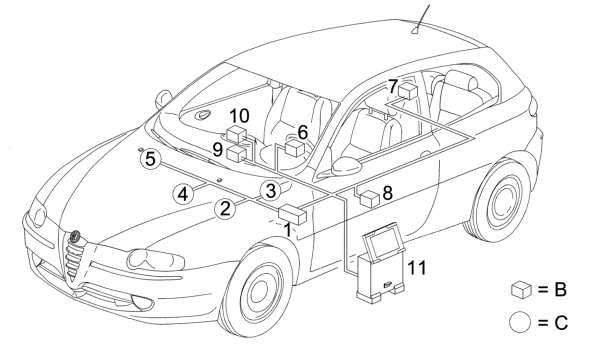
- 1 NBC Body Computer node
- 2 NFR brake system node
- 3 NAS steering angle node
- 4 NCM engine control node
- 5 NCR robotised transmission node
- 6 NQS instrument panel node
- 7 NVB boot compartment node
- 8 NPG driver's door node
- 9 NCL climate control system node
- 10 NIT/ NRR info-telematic node or radio node
- 11 NSD tester (examiner) node
- B = low speed CAN network
- C = high speed CAN network
The structure of the VENICE PLUS system is as follows:
‹ Prev Ve.n.i.ce (vehicle network integration component electronics) architectureNext › Operation of the multiplex network (ve.n.i.ce plus system)
Parts & tools for this job For 2000 Alfa Romeo 147
- TOOLDigital multimeterSearch: automotive digital multimeter
- PARTAssorted fuse kitSearch: car fuse assortment kit
- TOOLWire crimper and connector kitSearch: wire crimper connector kit
Links open Amazon search results in a new tab. As an Amazon Associate I earn from qualifying purchases.