
Engind front cover - r r
- Make
- Alfa Romeo
- Model
- GT Factory Service Manual
- Year
- 2003–2010
- Section
- Crankcase sump and covers › Engind front cover - r r
ENGIND FRONT COVER - R R
Removing
Proceed with the removal
Op. 1004D40 ENGINE - POSITION ON STAND AND REMOVE.
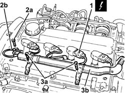
1. Disconnect the electrical connections from the ignition coils.
| Description | Connector | |
|---|---|---|
| 1 | Ignition coil | See A30 IGNITION ''COIL |
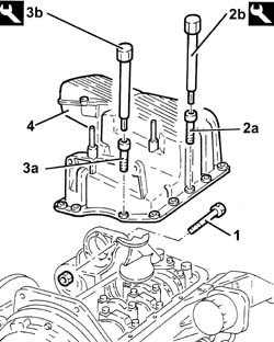
2. Undo the bolt (2a) and disconnect the earth lead (2b) from the cam cover.
3. Undo the bolts (3a) and remove the bulkhead coupling (3b) aside.
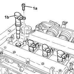
1. Undo the bolts (1a) and remove the ignition coils (1b).
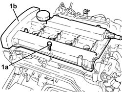
1. Undo the bolts (1a) and remove the cam cover (1b) complete with gasket.
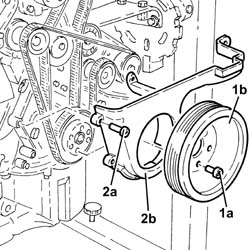
1. Undo the bolts (1a) and remove the crankshaft pulley (1b).
2. Undo the fixing bolts (2a) and remove the lower protective timing cover (2b).
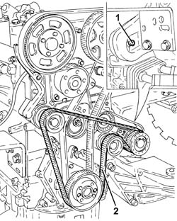
1. Loosen the counterrotating shaft toothed drive belt tensioner nut.
2. Release and remove the counterrotating shaft toothed timing drive belt.
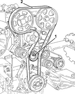
1. Loosen the nut retaining the timing belt moving tensioner.
2. Release and remove the toothed timing drive belt.
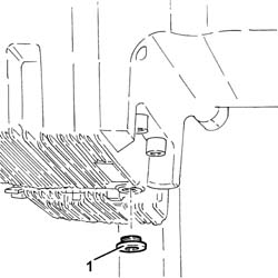
1. Undo the plug and drain the engine oil.
Collect the engine oil in a suitable container.
Rotate the engine through 180° on the overhaul stand.
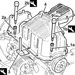
1. Undo the front and rear bolts (1a) fixing the crankcase sump using the tool (1b).
| Description | Code | |
|---|---|---|
| 1b | Spanner | 1.860.833.001 |
2. Undo the side bolts (2a) fixing the crankcase sump using the tool (2b).
| Description | Code | |
|---|---|---|
| 2b | Spanner | 1.860.834.001 |
3. Cut the crankcase sump sealant using the tool.
| Description | Code | |
|---|---|---|
| 3 | Blade | 1.870.718.000 |
4. Remove the crankcase sump.
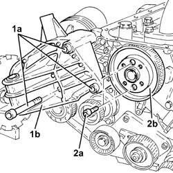
1. Undo bolts (1a) and remove the timing side rigid engine mount (1b).
2. Undo bolts (2a) and remove the counterrotating shaft toothed belt drive pulley (2b).
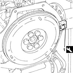
1. Fit the flywheel lock.
| Description | Code | |
|---|---|---|
| 1 | Counter-torque | 1.860.846.001 |
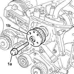
1. Undo the bolt (1a) (left hand thread) and remove the toothed drive pulley (1b).
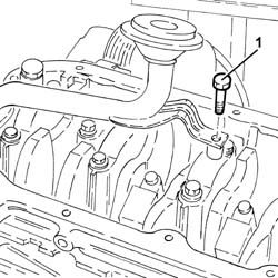
1. Unscrew the bolt securing the engine oil intake duct to the main bearing cap.
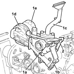
1. Undo the bolts (1a) and remove the engine block front cover (1b) with the built-in oil pump complete with intake chamber (1c), engine oil heat exchanger (1d) and engine oil filter (1e).
2. Remove the gasket.
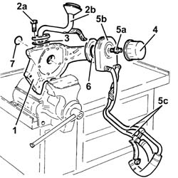
1. Position the front crankcase cover assembly in a vice with protective jaws.
2. Undo the bolts (2a) and remove the engine oil intake duct (2b).
3. Remove the gasket.
4. Remove the engine oil filter using a suitable tool.
5. Undo the nut (5a) and remove the engine oil heat exchanger (5b) complete with pipes (5c).
6. Remove the gasket.
7. Prise up the crankcase front cover oil seal.
Take care not to damage the oil seal seat during its removal.
Refitting
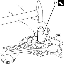
1. Fit the crankshaft front oil seal (1a) on the front crankcase cover using the tool (1b).
| Description | Code | |
|---|---|---|
| 1b | Fitting tool | 1.821.147.000 |
Position the front crankcase cover assembly in a vice with protective jaws.
Replace the engine oil heat exchanger complete with gasket and pipes in its seat and secure it using the pin.
Position the intake duct complete with gasket in its housing and secure it using the olts.
Rotate the engine through 180° on the overhaul stand.
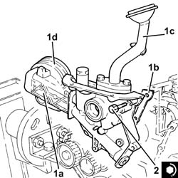
1. Refit the front crankcase cover (1a) with built-in oil pump with gasket (1b), inlet duct (1c) and engine oil heat exchanger (1d).
2. Tighten the bolts securing the crankcase front cover to the recommended torque.
| Fastening | Component | Ø | Value (daNm) | |
|---|---|---|---|---|
| 2 | Bolt | FRONT COVER CRANKSHAFT | M6 | (Engine crankcase side) 0.8 - 1.0 |
Srew the bolt securing the engine oil intake duct to the main bearing cap.
Lubricate the seal with engine oil and fit the engine oil filter tightening it fully by hand.
1. Position the toothed timing drive pulley (1a) in its housing and secure it tightening the bolt (anticlockwise) (1b) to the recommended torque.
| Fastening | Component | Ø | Value (daNm) | |
|---|---|---|---|---|
| 1b | Left hand bolt | DRIVE PULLEY(PULLIES) TIMING | M16 | (Crankshaft side) 20.9 - 23.1 |
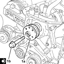
Remove the flywheel lock.
| Description | Code | |
|---|---|---|
| Counter-torque | 1.860.846.001 |
1. Place the timing side rigid engine support (1a) in its housing and secure it tightening the bolts (1b) to the recommended torque.
| Fastening | Component | Ø | Value (daNm) | |
|---|---|---|---|---|
| 1b | Bolt | RIGID ENGINE MOUNT, TIMING SIDE | M10 | (Engine crankcase side) 4.5 - 5.5 |
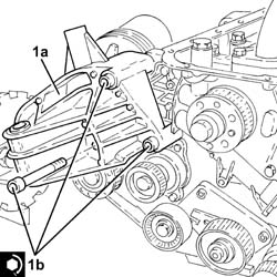
Apply silicon sealant to the entire perimeter of the crankcase sump.
1. Position the sump on the crankcase.
2. Tighten the front and rear bolts (2a) fixing the crankcase sump to the recommended torque using the tool (2b).
| Fastening | Component | Ø | Value (daNm) | |
|---|---|---|---|---|
| 2a | Front and rear bolts | OIL SUMP | M6 | (Engine crankcase side) 0.8 - 1.0 |
| Description | Code | |
|---|---|---|
| 2b | Spanner | 1.860.833.001 |
3. Tighten the side bolts (3a) fixing the crankcase sump to the recommended torque using the tool (3b).
| Fastening | Component | Ø | Value (daNm) | |
|---|---|---|---|---|
| 3a | Side bolts | OIL SUMP | M8 | (Engine crankcase side) 2.3 - 2.8 |
| Description | Code | |
|---|---|---|
| 3b | Spanner | 1.860.834.001 |
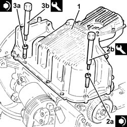
Tighten the engine oil drain plug to the recommended torque.
| Fastening | Component | Ø | Value (daNm) | |
|---|---|---|---|---|
| ENGINE OIL DRAIN PLUG | M18 | (Crankcase sump side) 1.8 - 2.2 |
Rotate the engine through 180° on the overhaul stand.
1. Fit the tool (1a) complete with dial gauge (1b) in the seat for the spark plug for cylinder no. 1.
| Description | Code | |
|---|---|---|
| 1a | Extension | 1.860.895.001 |
Rotate the crankshaft clockwise until the piston for cylinder no. 1 is at T.D.C. on the combustion stroke.
If TDC is exceeded, do not turn backwards but proceed with the rotation in the same direction rotating the crankshaft through another two revolutions and return the piston for cylinder no. 1 to TDC.
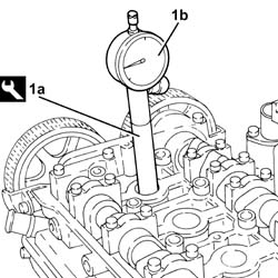
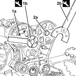
1. Undo the inlet side driven timing pulley bolts (1a) using the tool (1b) for counter-torque.
| Description | Code | |
|---|---|---|
| 1b | Counter-torque | 1.860.856.001 |
2. Undo the exhaust side driven timing pulley bolt (2a) using the tool (2b) for counter-torque.
| Description | Code | |
|---|---|---|
| 2b | Spanner for rotating timing pullies | 1.860.831.002 |
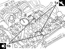
Undo the bolts and remove the inlet side camshaft fourth cap and the exhaust side camshaft second cap.
1. Fit the tool (1a) in place of the camshaft caps that have been removed and secure them tightening the bolts (1b) to the recommended torque.
Check that the camshaft cam profile and the tool are correctly aligned.
| Description | Code | |
|---|---|---|
| 1a | Templates | 1.870.859.000 |
| Fastening | Component | Ø | Value (daNm) | |
|---|---|---|---|---|
| 1b | Bolt | TEMPLATES FOR ENGINE TIMING | M7 | (Cylinder head side) 1.0 |
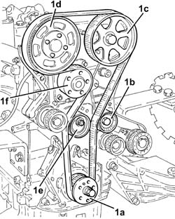
1. Fit the timing toothed drive belt in the following order:
toothed drive pulley (1a)
fixed tensioner (1b)
exhaust side toothed driven pulley (1c)
Before fitting the belt on the exhaust side toothed driven pulley, turn it clockwise (see figure) to the end of its travel.
inlet side toothed driven pulley (1d)
Before fitting the belt on the intake side toothed driven pulley, turn it clockwise (see figure) to the end of its travel.
moving tensioner (1e)
water pump pulley (1f).
Fit the belt with the arrow stamped on it facing the direction of rotation of the engine (clockwise - timing side).
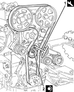
1. Use the tool to rotate the moving timing tensioner until the timing belt is completely taut.
| Description | Code | |
|---|---|---|
| 1 | Spanner | 1.822.149.000 |
2. Tighten the nut fixing the moving timing tensioner to the recommended torque.
| Fastening | Component | Ø | Value (daNm) | |
|---|---|---|---|---|
| 2 | Nut | MOBILE TIMING TENSIONER | M8 | 2.3 ÷ 2.8 |
1. Tighten the bolts (1a) for the inlet side toothed timing driven pulley to the specified torque using tool (1b) for counter-torque.
| Fastening | Component | Ø | Value (daNm) | |
|---|---|---|---|---|
| 1a | Bolt | TIMING DRIVEN PULLIES | M6 | (Inlet camshaft side) 0.8 - 1.0 |
| Description | Code | |
|---|---|---|
| 1b | Counter-torque | 1.860.856.001 |
2. Tighten the exhaust side driven timing pulley bolt (2a) to the specified torque using the tool (2b) for counter-torque.
| Fastening | Component | Ø | Value (daNm) | |
|---|---|---|---|---|
| 2a | Bolt | TIMING DRIVEN PULLIES | M12 | (Exhaust camshaft side) 10.8 - 13.2 |
| Description | Code | |
|---|---|---|
| 2b | Spanner for rotating timing pullies | 1.860.831.002 |
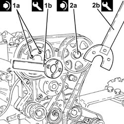
Remove the camshaft timing tools.
| Description | Code | |
|---|---|---|
| Templates | 1.870.859.000 |
Place the camshaft caps previously removed in their housings and secure them tightening the bolts to the recommended torque.
| Fastening | Component | Ø | Value (daNm) | |
|---|---|---|---|---|
| Bolt | CAMSHAFT SUPPORTS | M7 | (Cylinder head side) 1.4 - 1.7 |
Turn the crankshaft through two turns in its direction of rotation (clockwise - timing side) and move the cylinder no. piston to TDC.
1. Insert tool (1a) to hold the mobile timing tensioner still and loosen tensioner nut (1b).
| Description | Code | |
|---|---|---|
| 1a | Spanner | 1.822.149.000 |
2. Turn tool (2a) anticlockwise (timing side) to align tensioner mobile pointer (2b) with reference hole (2c).
| Description | Code | |
|---|---|---|
| 2a | Spanner | 1.822.149.000 |
3. Tighten the nut fixing the moving timing tensioner to the recommended torque.
| Fastening | Component | Ø | Value (daNm) | |
|---|---|---|---|---|
| 3 | Nut | MOBILE TIMING TENSIONER | M8 | 2.3 ÷ 2.8 |
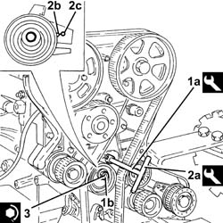
Turn the crankshaft through two revolutions in its direction of rotataion (clockwise - timing side) to move the first cylinder to TDC in the combustion phase and check the engine timing is correct using the tool.
| Description | Code | |
|---|---|---|
| Templates | 1.870.859.000 |
Remove the tool for checking T.D.C. from the housing for the spark plug for cylinder no.1.
| Description | Code | |
|---|---|---|
| Extension | 1.860.895.001 |
Place the spark plug for cylinder no.1 in its housing and tighten it to the recommended torque.
| Fastening | Component | Ø | Value (daNm) | |
|---|---|---|---|---|
| SPARK PLUGS | M14 | (Cylinder head side) 2.4 - 3.0 |
Position the counterrotating shaft toothed belt drive pulley in its housing and secure it tightening the bolts to the recommended torque.
| Fastening | Component | Ø | Value (daNm) | |
|---|---|---|---|---|
| Bolt | COUNTER-ROTATING SHAFT DRIVE PULLEY | M6 | (Timing belt drive pulley side) 0.8÷1.0 |
1. Turn the counterrotating shafts so that the notches (1a) on the pulleys are aligned with ribs (1b).
2. Fit the lower timing belt protective cover and the crankshaft pulley and check the notches stamped on them are aligned.
Fit the counterrotating shaft toothed drive belt
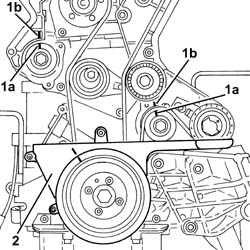
1. Tension the counterrotating shaft drive belt using tool (1a) to move reference hole (1b) on the tensioner to the centre of the rotation sector.
| Description | Code | |
|---|---|---|
| 1a | Spanner | 1.822.154.000 |
2. Tighten the nut fixing the counterrotating shaft toothed belt tensioner to the recommended torque.
| Fastening | Component | Ø | Value (daNm) | |
|---|---|---|---|---|
| 2 | Nut | DRIVEBELT TENSIONER COUNTER-ROTATING SHAFT | M6 | (Left counter-rot. shaft front cover side) 0.8÷1.0 |
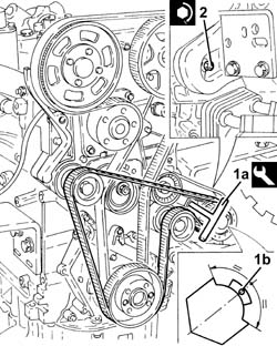
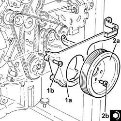
1. Refit the lower timing belt covers (1a) and secure them using the bolts (1b).
2. Position the crankshaft pulley (2a) in its housing and secure it tightening the bolts (2b) to the recommended torque.
| Fastening | Component | Ø | Value (daNm) | |
|---|---|---|---|---|
| 2b | Bolt | CRANKSHAFT PULLEY | M8 | 2.3 ÷ 2.8 |
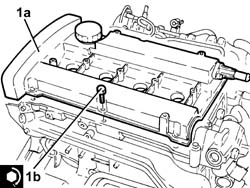
1. Place the cam cover (1a), complete with gasket, back in its housing and secure it tightening the bolts (1b) to the recommended torque.
| Fastening | Component | Ø | Value (daNm) | |
|---|---|---|---|---|
| 1b | Bolt | CAM COVER | M6 | (Cylinder head side) 0.8 - 1.0 |
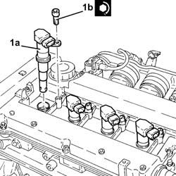
1. Replace the ignition coils (1a) in their housings and secure them tightening the bolts (1b) to the recommended torque.
| Fastening | Component | Ø | Value (daNm) | |
|---|---|---|---|---|
| 1b | Bolt | IGNITION COIL/REEL | M6 | (Cam cover side) 0.8 ÷ 1.0 |
Fit the bulkhead coupling in its housing and secure it using the bolts.
Connect the battery earth lead to the cam cover and secure it using the bolt.
Connect the electrical connections to the ignition coils.
Proceed with the refitting
Op. 1004D40 ENGINE - POSITION ON STAND AND REMOVE.
Removing
1. Fit the tool.
| Description | Code | |
|---|---|---|
| 1 | Counter-torque | 1.820.624.000 |
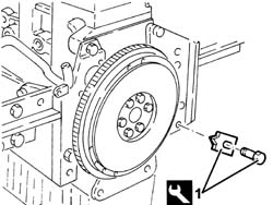
1. Loosen the bolt retaining the timing pulley.
Remove the tool.
| Description | Code | |
|---|---|---|
| Counter-torque | 1.820.624.000 |
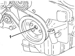
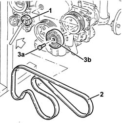
1. Adjust the automatic belt tensioner using the tool to slacken the auxililary drivebelt.
2. Remove the auxiliary drive belt.
3. Undo the bolt (3a) and remove the auxiliary drive belt fixed tensioner (3b).
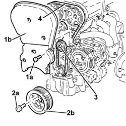
1. Undo the bolts (1a) and remove the upper timing belt guard (1b).
2. Undo the nut (2a) and remove the auxiliary drive belt pulley (2b).
3. Loosen the timing belt tensioner nut.
4. Remove the timing belt.
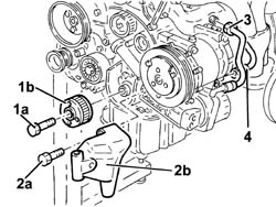
1. Completely undo the bolt (1a) loosened previously and remove the timing belt drive pulley (1b).
2. Undo the bolts (2a) and remove the timing side rigid engine mount (2b).
3. Disconnect the water outlet hose fitting from the water/oil heat exchanger.
4. Disconnect the water inlet hose in the water-oil heat exchanger.
Rotate the engine through 180° on the overhaul stand.
1. Unscrew the bolt connecting the crankcase sump to the intermediate driveshaft mount.
2. Undo the front and rear bolts (2a) fixing the crankcase sump using the tool (2b).
| Description | Code | |
|---|---|---|
| 2b | Spanner | 1.822.145.000 |
3. Undo the side bolts (3a) fixing the crankcase sump using the tool (3b).
| Description | Code | |
|---|---|---|
| 3b | Spanner | 1.822.144.000 |
4. Remove the crankcase sump.
To release the crankcase sump, tap it gently using a wooden or resin hammer, then use a screwdriver for leverage in the projections at the sides of the sump.
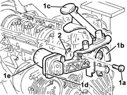
1. Undo the bolts (1a) and remove the oil pump (1b) with with intake chamber (1c), water - oil heat exchanger (1d) and engine oil filter (1e).
2. Remove the seal.
Remove the crankshaft front oil seal.
Refitting
Fit the oil pump with intake chamber, water-oil heat exchanger, oil filter and a new gasket and secure by tightening the bolts to the specified torque.
| Fastening | Component | Ø | Value (daNm) |
|---|
1. Fit a new crankshaft front oil seal (1a) using the tool (1b).
| Description | Code | |
|---|---|---|
| 1b | Fitting tool | 1.821.247.000 |
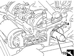
Apply silicon sealant to the entire perimeter of the crankcase sump.
Fit the crankcase sump.
ighten the front and rear bolts fixing the crankcase sump to the recommended torque using the tool.
| Fastening | Component | Ø | Value (daNm) |
|---|
| Description | Code | |
|---|---|---|
| Spanner | 1.822.145.000 |
Tighten the side bolts fixing the crankcase sump to the recommended torque using the tool.
| Fastening | Component | Ø | Value (daNm) |
|---|
| Description | Code | |
|---|---|---|
| Spanner | 1.822.144.000 |
Tignten the bolt connecting the crankcase sump to the intermediate driveshaft mount.
Rotate the engine through 180° on the overhaul stand.
Connect the water intake pipe in the water-oil heat exchanger and secure with the collar.
Tighten the water outlet hose fitting from the water/oil heat exchanger.
Fit the timing side power unit mount and secure it using the bolts.
Fit the timing belt drive pulley and secure with the bolt without tightening.
1. Disconnect the electrical connections from the ignition coils.
| Description | Connector | |
|---|---|---|
| 1 | Ignition coil | A30 |
2. Disconnect the earth lead from the cylinder head.
3. Disconnect the high tension leads (3a) from the spark plugs using tool (3b).
| Description | Code | |
|---|---|---|
| 3b | Caliper | 1.820.636.000 |
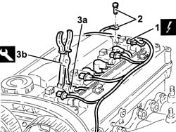
Undo the botls and remove the bracket complete with ignition coils and high tension leads.
Undo the bolts and remove the cam cover (2b) complete with gasket.
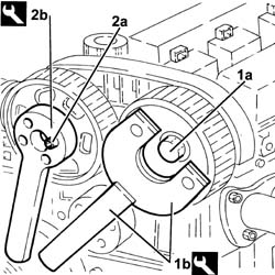
1. Loosen the bolt (1a) for the exhaust side driven timing pulley using tools (1b) for counter-torque.
| Description | Code | |
|---|---|---|
| 1b | Counter-torque | 1.822.146.000 |
| Description | Code | |
|---|---|---|
| 1b | Counter-torque | 1.822.156.000 |
2. Loosen the bolts (2a) for the inlet side camshaft pulley using tool (2a) for counter-torque.
| Description | Code | |
|---|---|---|
| 2b | Counter-torque | 1.822.155.000 |
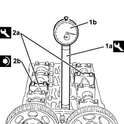
1. Fit the tool (1a) complete with dial gauge (1b) in the seat for the spark plug for cylinder no. 1.
| Description | Code | |
|---|---|---|
| 1a | Extension | 1.825.013.000 |
Rotate the crankshaft until the piston for cylinder no. 1 is at T.D.C. on the combustion stroke.
Unscrew the bolts and remove the third cap on the intake and exhaust camshafts.
2. Fit tool (2a) in place of the camshaft caps that have been removed and secure them tightening the bolts (2b) to the recommended torque.
Check that the camshaft cam profile and the tool are correctly aligned.
| Description | Code | |
|---|---|---|
| 2a | Templates | 1.870.734.000 |
| Fastening | Component | Ø | Value (daNm) | |
|---|---|---|---|---|
| 2b | Bolt | TEMPLATES FOR ENGINE TIMING | M7 | (Cylinder head side) 1.0 |
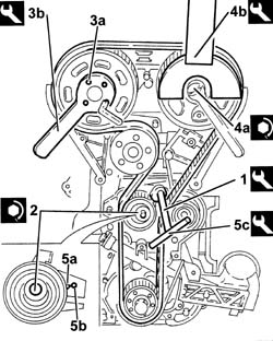
Fit the timing belt.
1. Apply maximum tension to the timing belt using tool.
| Description | Code | |
|---|---|---|
| 1 | Spanner | 1.822.149.000 |
2. Tighten the belt tensioner nut to the recommended torque.
| Fastening | Component | Ø | Value (daNm) | |
|---|---|---|---|---|
| 2 |
3. Tighten the bolts (3a) for the inlet side toothed timing drive pulley to the specified torque using tool (3b) for counter-torque.
| Fastening | Component | Ø | Value (daNm) | |
|---|---|---|---|---|
| 3a |
| Description | Code | |
|---|---|---|
| 3b | Counter-torque | 1.822.155.000 |
4. Tighten the bolt (4a) for the exhaust side toothed timing drive pulley to the specified torque using tools (4b) for counter-torque.
| Fastening | Component | Ø | Value (daNm) | |
|---|---|---|---|---|
| 4a |
| Description | Code | |
|---|---|---|
| 4b | Counter-torque | 1.822.146.000 |
| Description | Code | |
|---|---|---|
| 4b | Counter-torque | 1.822.156.000 |
Undo the bolts and remove the tool.
| Description | Code | |
|---|---|---|
| Templates | 1.870.734.000 |
Fit the camshaft cams removed previously and tighten the bolts to the recommended torque.
| Fastening | Component | Ø | Value (daNm) |
|---|
Turn the crankshaft through two revolutions.
Loosen the timing belt tensioner nut.
5. Align the mobile pointer (5a) on the timing belt with reference hole (5b) using tool (5c).
| Description | Code | |
|---|---|---|
| 5c | Spanner | 1.822.149.000 |
Tighten the belt tensioner nut to the recommended torque.
| Fastening | Component | Ø | Value (daNm) |
|---|
Remove the tool complete with dial gauge.
| Description | Code | |
|---|---|---|
| Extension | 1.825.013.000 |
Fit the spark plug for cylinder no. 1.
Fit the cam cover complete with gasket and secure it using the bolts.
Fit the bracket complete with ignition coils and high tension leads and secure using the bolts.
Connect the spark plug high tension leads.
Connect the earth lead to the cylinder head.
Connect the electrical connections to the ignition coils.
Fit the upper timing belt guard and secure it using the bolts.
Fit the auxiliary drive belt drive pulley and secure it tightening the bolts to the recommended torque.
| Fastening | Component | Ø | Value (daNm) |
|---|
Fit the auxiliary drive belt fixed tensioner and secure it with the bolt.
Fit the auxiliary drive belt by prising over the autumatic belt tensioner using a wrench.
Fit the tool.
| Description | Code | |
|---|---|---|
| Counter-torque | 1.820.624.000 |
Tighten the timing belt pulley bolt to the specified torque.
| Fastening | Component | Ø | Value (daNm) |
|---|
Remove the tool.
| Description | Code | |
|---|---|---|
| Counter-torque | 1.820.624.000 |
Parts & tools for this job For 2003 Alfa Romeo GT
- PARTEngine gasket setSearch: Alfa Romeo GT 2003 engine gasket set
- TOOLTorque wrenchSearch: 3/8 inch torque wrench
- TOOLFeeler gauge setSearch: feeler gauge set
Links open Amazon search results in a new tab. As an Amazon Associate I earn from qualifying purchases.