
Fuel level gauge
- Make
- Alfa Romeo
- Model
- GTV / Spider GTV and Spider (916) Factory Service Manual
- Year
- 1995–2000
- Section
- Fuel supply (V6) › Fuel level gauge
10 Engine – 3.0 V6Fuel level gauge
- Position a hydraulic bracket under the tank.
- Slacken the fastening screws of the fuel tank metal support straps, then remove the tank lowering the hydraulic jack.
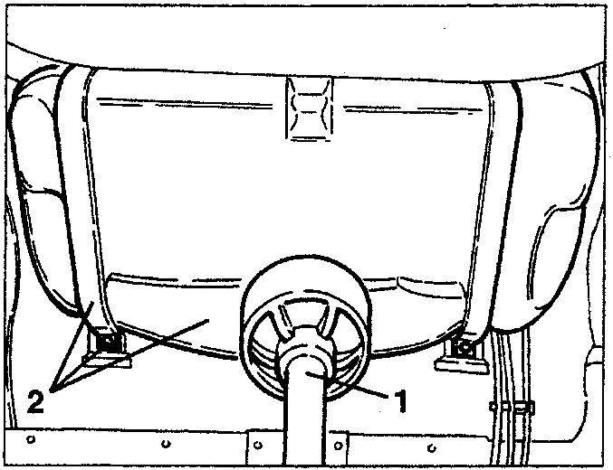
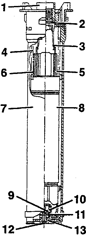
FUEL LEVEL GAUGE
This is of the axial floating type and it is fastened to the tank by a bayonet coupling.
Its main feature is that it prevents the gauge pointer from swaying when cornering and on twisting roads. This is because the float that runs inside the tube of the level gauge is submerged in the fuel and is therefore only sensitive to the hydrostatic thrust and not to the differences in level due to swaying of the vehicle.
- Connector
- O-Ring
- Sliding blade
- Resistance
- Common blade
- Upper spring
- Tube
- Float
- Adjustment pin
- Lower spring
- Cup
- Cap
- Base
REMOVING/REFITTING
- Disconnect the battery (-) terminal.
- Raise the rearscreen of the top and open the top upper lid.
- Move aside the top compartment trim, then slacken the fastening nuts and remove the lid to gain access to the pump and to the fuel level gauge.
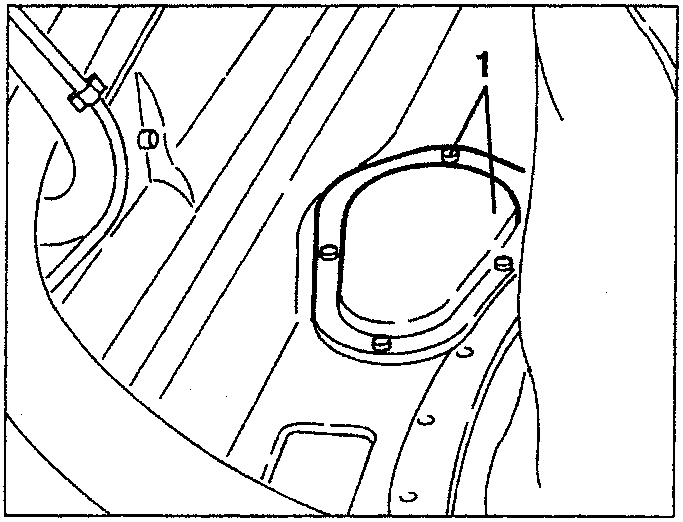
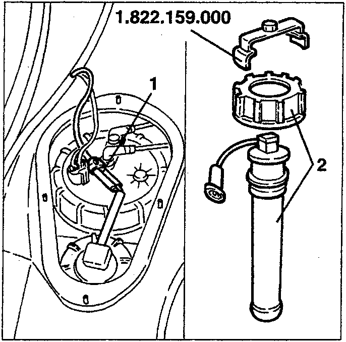
- Disconnect the electrical connection of the fuel level gauge.
- Using tool no. 1.822.159.000, slacken the locknut and remove the fuel level gauge complete with seal.
CHECKS AND INSPECTIONS
For a complete functional check, see GROUP 55 - ELECTRIC SYSTEM DIAGNOSIS.
Parts & tools for this job For 1995 Alfa Romeo GTV / Spider
- PARTEngine gasket setSearch: Alfa Romeo GTV / Spider 1995 engine gasket set
- TOOLTorque wrenchSearch: 3/8 inch torque wrench
- TOOLFeeler gauge setSearch: feeler gauge set
Links open Amazon search results in a new tab. As an Amazon Associate I earn from qualifying purchases.