
Pulse damper
- Make
- Alfa Romeo
- Model
- GTV / Spider GTV and Spider (916) Factory Service Manual
- Year
- 1995–2000
- Section
- Fuel supply (V6) › Pulse damper
PULSE DAMPER
The pulse damper is connected to the inlet of the fuel distributor and it serves to suppress the pulsing noises that can occur especially at low engine rpm. The pulsing is generated by pressure differences of the fuel deriving from the opening and closing of the electroinjectors or of the pressure regulator.
REMOVAL/REFITTING
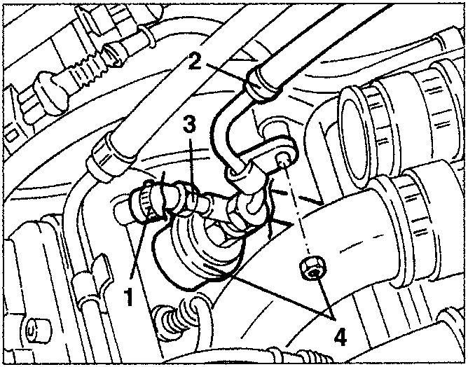
- Remove the intake manifold of cylinder no. 4.
- Disconnect the fuel distributor manifold connection pipe.
- Disconnect the fuel inlet pipe from the pulse damper.
- Disconnect the pulse damper from the fuel distributor manifold slackening its coupling.
- Slacken the nut of the fastening clamp and remove the pulse damper complete with stiff pipes.
ELECTROINJECTORS
The injector nozzle is formed so that the jet of fuel atomizes into a 30° cone. The injectors are locked by the fuel distributor which presses them into their housings machined on the intake ducts. The injectors are also anchored to the fuel distributor by "safety catches" and sealed by two O-Rings. The electroinjectors have the task of metering the amount of fuel needed by the engine. They are "all or nothing" devices i.e. they only have two possible conditions, either open or closed.
They will let the fuel pass when they are "open" and prevent it from being delivered when they are "closed". They basically comprise a nozzle controlled by an electromagnet and by a return spring. In the rest position, the needle, which forms one piece with the core, is pushed by the spring onto the electroinjector nose to close the hole and ensure that unwanted fuel is unable to come out. As soon as the winding is energized, the core is attracted, it compresses the spring opening the nozzle hole, thereby allowing the fuel to flow out. Considering the physical characteristics of the fuel (viscosity, density) and the pressure difference (pressure regulator) constant, the amount of fuel injected depends on the injector opening time only. The winding energizing time is normally called the "injection time".
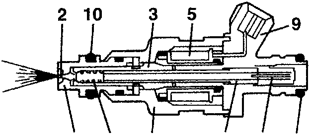
- Injector body
- Needle
- Magnetic core
- Helical spring
- Winding
- Injector nose
- Adjustable pressure plate
- Filter
- Electrical connection
- Seal rings
CHECKING FOR CORRECT OPENING OF ELECTROINJECTORS
- Measure the quantity of CO at the exhaust. - Disconnect the electroinjector connectors one by one; each time measure for a reduction of the CO quantity at the exhaust and check that this value remains constant at each check. - If not, locate and replace the faulty electroinjector; in any case a visual index of the efficiency of the electroinjectors is given by the spark plug electrodes: • a mixture which is too rich corresponds to a black colour. • a mixture which is too lean corresponds to a light colour.
Parts & tools for this job For 1995 Alfa Romeo GTV / Spider
- PARTEngine gasket setSearch: Alfa Romeo GTV / Spider 1995 engine gasket set
- TOOLTorque wrenchSearch: 3/8 inch torque wrench
- TOOLFeeler gauge setSearch: feeler gauge set
Links open Amazon search results in a new tab. As an Amazon Associate I earn from qualifying purchases.