
Fuel pump
- Make
- Alfa Romeo
- Model
- GTV / Spider GTV and Spider (916) Factory Service Manual
- Year
- 1995–2000
- Section
- Fuel supply (V6) › Fuel pump
FUEL PUMP
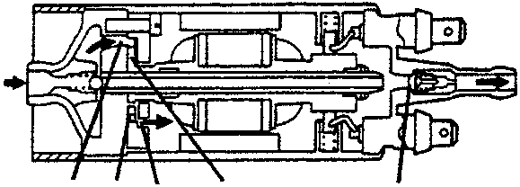
The electric pump, submerged in the tank is of the volumetric displacement type with rollers (4), with brush motor and excitation by permanent magnets. The impeller (2) turns, pulled by the motor, creating volumes which move from the inlet port (1) to the delivery port (5). These volumes are delineated by the rollers which during the rotation of the motor adhere to the outer ring.
The pump is fitted with two valves: one is a check valve (3) to prevent the fuel circuit from emptying, when the pump is not operating; the second is an overpressure valve which short circuits the delivery with the inlet when pressures build up above 5 bar, thereby avoiding overheating the electric motor. The supply contacts are polarised to prevent the connections from being inverted.
REMOVING/REFITTING
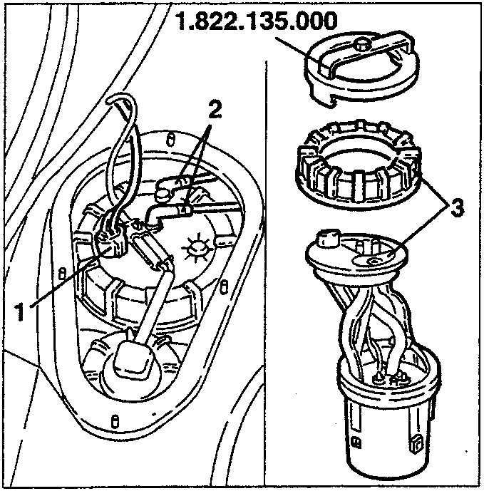
Proceed as described in the first three steps of the procedure "FUEL LEVEL GAUGE - Removing/Refitting".
- Disconnect the electrical connection of the fuel pump.
- Disconnect the fuel delivery and return pipes from the pump.
- Using tool 1.822.135.000, slacken the locknut fa-stening the fuel pump, then withdraw it from its hous-ing complete with seal.
DIS-ASSEMBLY/RE-ASSEMBLY
- Disconnect the two electrical connections from the fuel pump.
- Disconnect the excess fuel return pipe from the pump tray.
- Disconnect the delivery pipe from the fuel pump.
- Prise the end of the spring, then separate the cover from the pump.
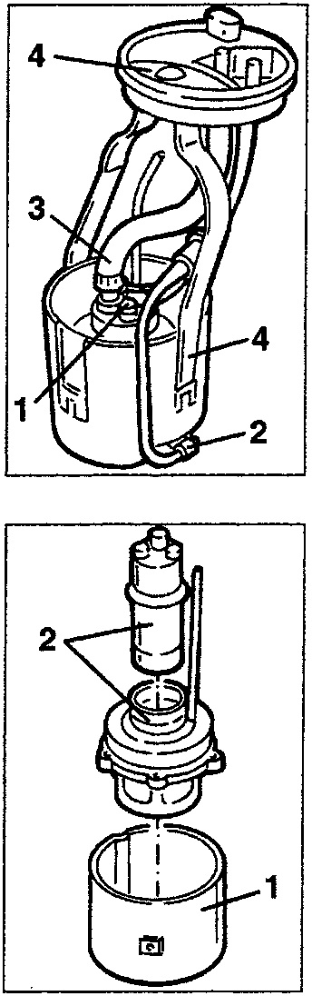
- Withdraw the tray from the fuel pump assembly.
- Slacken the fastening clamp and withdraw the fuel pump from the filte-ring support.
CHECKS AND INSPECTIONS
Accurately clean the mesh filter. The presence of water in the fuel is particularly har-mful to the pump as it causes inside rust. Carefully check the operation of the pump if the fuel is contami-nated with water.
Also check the efficiency of the supply contacts since any rust would reduce the voltage at their terminals, thereby reducing delivery resulting in the formation of bubbles and reduction of the fuel injected.
NOTE: In the event of replacement, remember that the pump is supplied filled with protective oil and with the unions closed by special plugs. When installing on the vehicle, it is not necessary to empty the pump as the oil is burnt in the engine. If the protective oil is emptied from the pump, it is necessary to put it into operation within two we-eks to prevent the formation of a film of dry oil on the motor collector which would ruin it due to the lack of electrical continuity.
Parts & tools for this job For 1995 Alfa Romeo GTV / Spider
- PARTFuel filterSearch: Alfa Romeo GTV / Spider 1995 fuel filter
- TOOLFuel pressure test kitSearch: fuel pressure test kit
- TOOLFuel line disconnect toolSearch: fuel line disconnect tool
Links open Amazon search results in a new tab. As an Amazon Associate I earn from qualifying purchases.