
Instrument Panel (IP): Specifications (page 2 of 2)
- Make
- Aston Martin
- Model
- DB9 Factory Workshop Manual
- Year
- Issue 2, 2005
- Section
- Instrument Panel (IP)
01 Body systemSpecifications · page 2 of 2
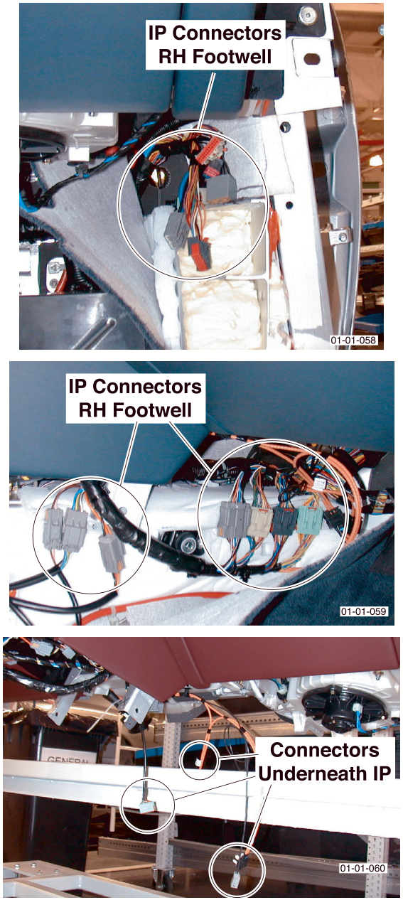
13. Manual Gearbox Only.
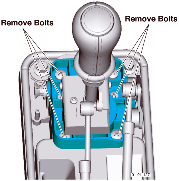
Remove the gear-lever.
- Disengage the manual shift control cables (x2).
- Remove screws (x6) that secure the gear lever pivot block. Withdraw the gear lever.
- Remove, L/H and R/H, bolts securing the IP to vehicle.
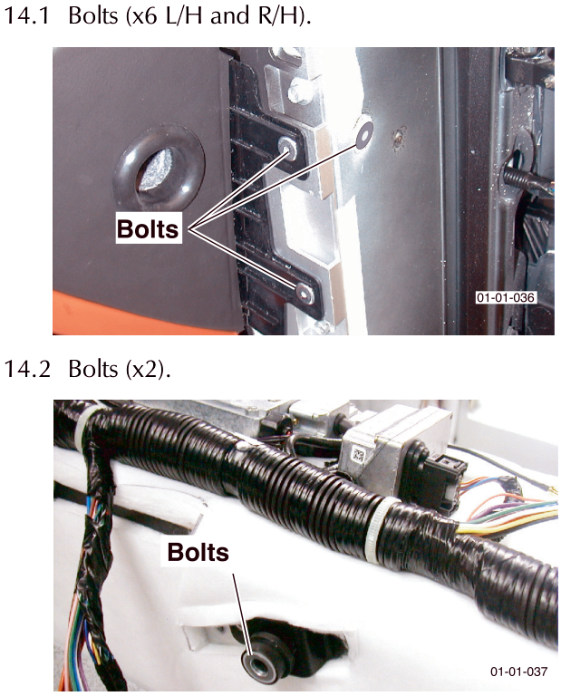
14.1 Bolts (x6 L/H and R/H).
14.2 Bolts (x2).
Parts & tools for this job For 2005 Aston Martin DB9
- TOOLTrim removal tool kitSearch: trim removal tool kit
- PARTTouch-up paintSearch: Aston Martin touch up paint
- PARTPanel clip assortmentSearch: Aston Martin panel clips assortment
Links open Amazon search results in a new tab. As an Amazon Associate I earn from qualifying purchases.