
Controls
- Make
- Fiat
- Model
- Bravo /Brava (182) Factory Service Manual
- Year
- 1995–2001
- Section
- Climate control (98 range) › Controls
CONTROLS
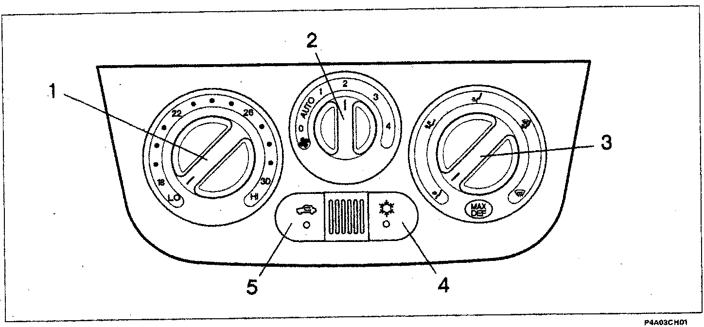
The left knob (1) is for selecting the REQUESTED TEMPERATURE (between 18 and 30 °C): it is connected to a potentiometer which detects the various angular positions and transmits a signal to the electronic control unit for a total of 15 different positions (one per degree centigrade) with two extreme positions "LO" and "HI" corresponding to the maximum cold and maximum hot settings, respectively.
The centre knob (2) is for adjusting the AIR VENTILATION: it is also connected to a potentiometer which detects the various angular positions and sends a signal to the electronic control unit. There are four possible air flow rates which can be set manually (1, 2, 3 and 4), whilst in the "AUTO" position the system itself automatically selects the most suitable flow rate for reaching or maintaining the desired temperature.
NOTE Position "0" indicates minimal ventilation: the fan is off and there is only a slight flow of air at the vents.
With the compressor on, the fan is always "forced" at the first speed, even with the knob at "0".
NOTE There are two different maps inside the control unit which correlate the air flow rate and the speed of the fan: the pollen filter on the outside air inlet ensures that the flow rate is lower - in relation to the fan speed - in the "dynamic air" condition compared with the "recirculation" condition.
The right knob (3) is for selecting the FLOW DISTRIBUTION for the air towards the passenger compartment and is achieved in five different ways: the selection is made manually via a cable which controls the movement of the distribution flaps.
Pressing button (4) enables the operation of the COMPRESSOR (air refrigeration circuit); if the button is released, the operation ceases. Engagement is entirely manual: the compressor is only always enabled in the "MAX DEF" setting even with the button released.
Pressing button (5) engages the AIR RECIRCULATION function inside the passenger compartment; releasing the button produces a "dynamic" air flow from the outside.
Engagement is entirely manual: the recirculation function is only excluded in the "MAX DEF" setting even if the button is pressed.
Parts & tools for this job For 1995 Fiat Bravo
- TOOLA/C manifold gauge setSearch: AC manifold gauge set
- TOOLUV leak detection kitSearch: AC UV leak detection kit
- PARTCabin filterSearch: Fiat Bravo 1995 cabin filter
Links open Amazon search results in a new tab. As an Amazon Associate I earn from qualifying purchases.