
Frost sensor
- Make
- Fiat
- Model
- Bravo /Brava (182) Factory Service Manual
- Year
- 1995–2001
- Section
- Climate control (98 range) › Frost sensor
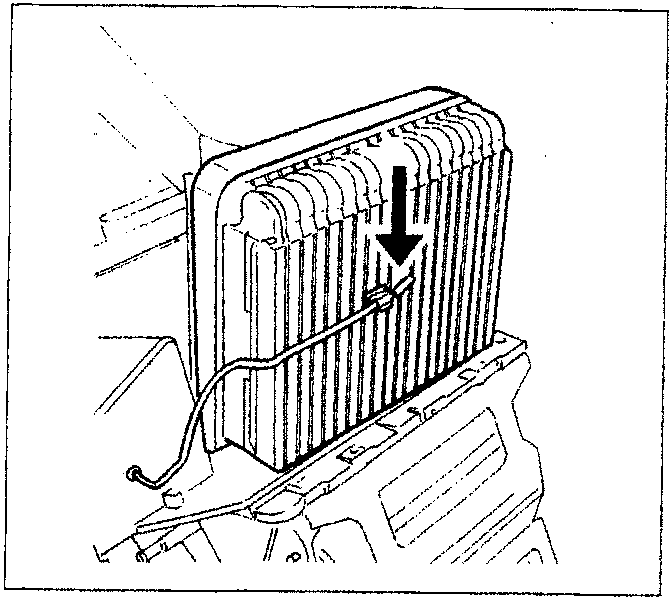
Frost sensor
The frost sensor is located inside the duct-distributor assembly, fitted directly on the evaporator and detects the temperature warning the control unit, if necessary, to switch off the compressor to avoid freezing. It consists of NTC sensor (R at 25°C = 10 kOhm), with an operating range of between -5°C and +25°C.
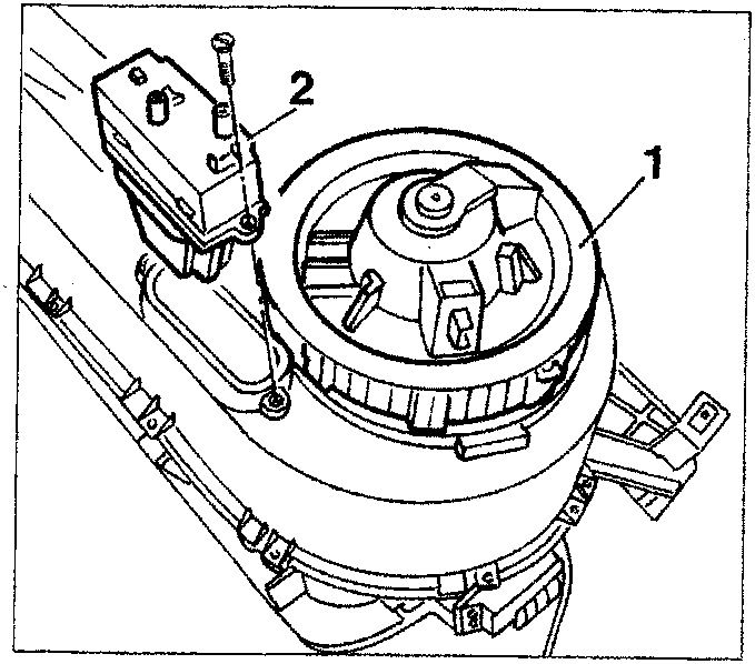
Electric fan with electronic speed regulator
This fan which sends the outside or recirculation air towards the duct-distributor receives a 12 V supply and is operated at different speeds continuously by an electronic regulator positioned nearby.
- Electric fan
- Electronic regulator
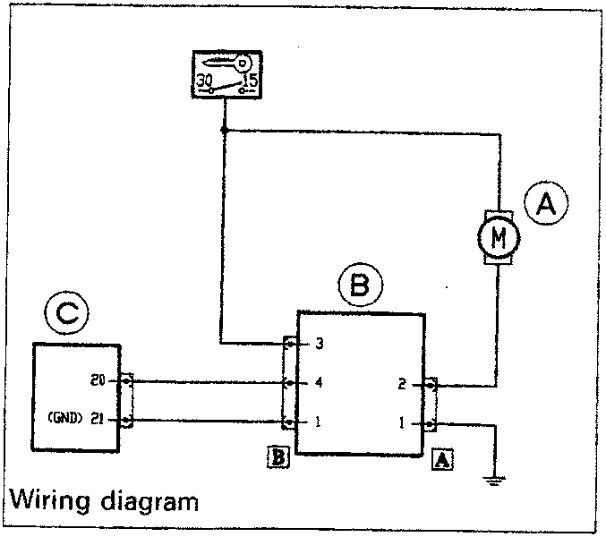
The electronic regulator receives an input signal from the control unit and transforms it into a continuously variable power earth signal to operate the fan.
- Electric fan
- Electronic regulator
- Electronic control unit
Parts & tools for this job For 1995 Fiat Bravo
- TOOLOBD2 scannerSearch: OBD2 scanner
- TOOLDigital multimeterSearch: automotive digital multimeter
- TOOLBack-probe test leadsSearch: back probe test leads
Links open Amazon search results in a new tab. As an Amazon Associate I earn from qualifying purchases.