
Requested air flow rate potentiometer
- Make
- Fiat
- Model
- Bravo /Brava (182) Factory Service Manual
- Year
- 1995–2001
- Section
- Climate control (98 range) › Requested air flow rate potentiometer
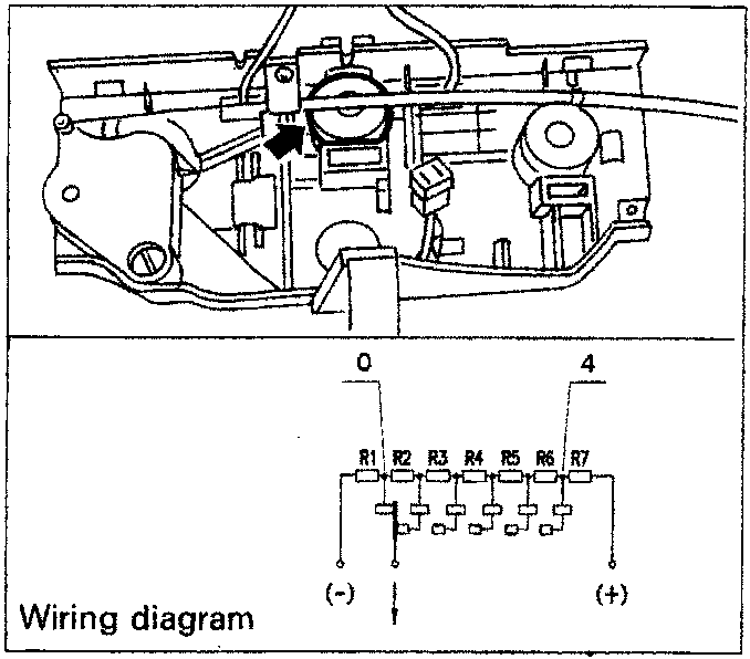
Wiring diagram
Requested air flow rate potentiometer
This potentiometer is connected to the air ventilation knob and detects the various angular positions, sending a signal to the electronic control unit: there are four possible air flow rates which are set manually (1, 2, 3 e 4), plus an "AUTO" position and "0".
It receives a 5V supply from the control unit and has a controlled earth and gives off a signal corresponding to the position of the knob:
R1-R7=1500 Ohm±1%
Recirculation function switch
Pressing this switch engages the recirculation function which is managed completely manually:
Compressor enablement switch (air refrigeration circuit)
Pressing this switch enables the operation of the compressor (air refrigeration circuit).
Passenger compartment temperature sensor
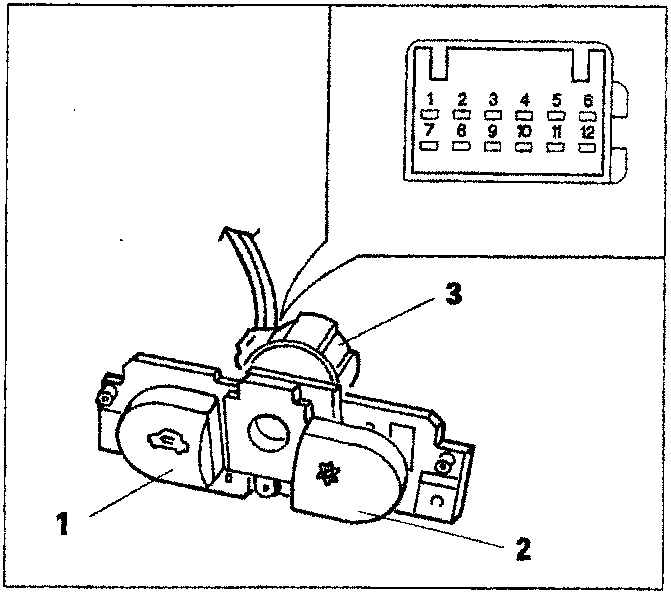
- Recirculation function switch
- Compressor enablement switch
- Passenger compartment temperature sensor
This is located in the climate control control panel between the recirculation and compressor switches.
It consists of an NTC sensor (R at 25°C = 2.2 kOhm), with an operating range of between +5°C and +45°C. The sensor is "ventilatated", in other words it incorporates a small fan which is always supplied so that the temperature reading is not affected by stagnant air inside the dashboard giving a misleading picture.
These last three components make up a single element which is connected by a single connector.
| Terminal | FUNCTION |
|---|---|
| 1 | Motor for ventilated sensor (+) |
| 2 | Motor for ventilated sensor (-) |
| 3 | Earth for passenger compartment temperature sensor |
| 4 | Signal for passenger compartment temperature sensor |
| 5 | MAX-DEF |
| 6 | N.C. |
| Terminal | FUNCTION |
|---|---|
| 7 | Compressor operation |
| 8 | Warning lights operation (NC) |
| 9 | +15 |
| 10 | Ideogram lights (+) |
| 11 | Ideogram lights (-) |
| 12 | Recirculation control |
Parts & tools for this job For 1995 Fiat Bravo
- TOOLA/C manifold gauge setSearch: AC manifold gauge set
- TOOLUV leak detection kitSearch: AC UV leak detection kit
- PARTCabin filterSearch: Fiat Bravo 1995 cabin filter
Links open Amazon search results in a new tab. As an Amazon Associate I earn from qualifying purchases.