
Marelli a127i 14v 50/85a alternator
- Make
- Fiat
- Model
- Bravo /Brava (182) Factory Service Manual
- Year
- 1995–2001
- Section
- Recharging › Marelli a127i 14v 50/85a alternator
55 Electrical systemMarelli a127i 14v 50/85a alternator
MARELLI A127I 14V 50/85A ALTERNATOR
(versions with 1747 16V; 1998 20V; 1910 TD engines)
Removing-refitting (1747 16V version)
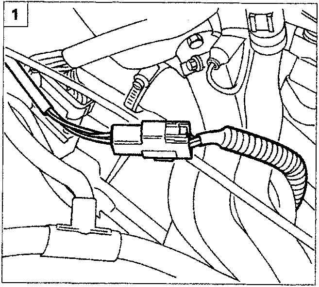
- Position the vehicle on a lift and disconnect the connector for the Lambda sensor.
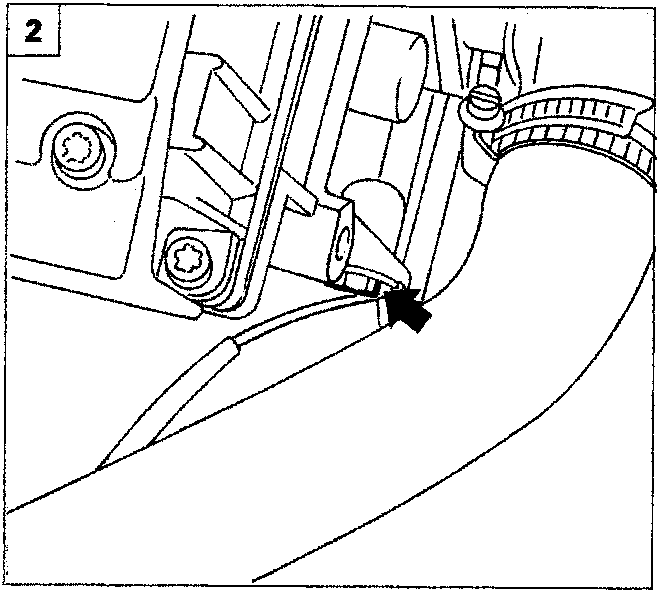
- Undo the bolt shown and release the wiring for the Lambda sensor.
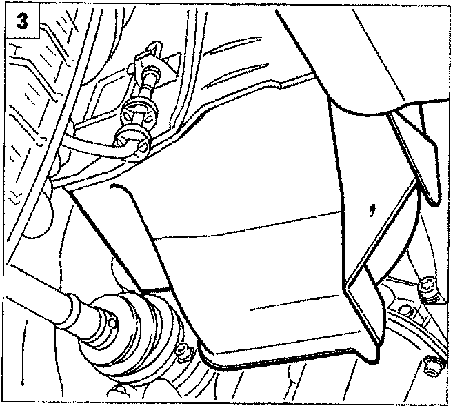
- Raise the vehicle and remove the wheel arch liner after having undone the fixing bolts, then remove the belt.
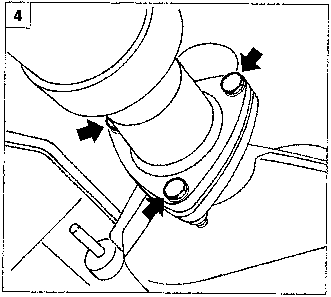
- Remove the fixing the first section of the exhaust pipe to the catalytic converter.
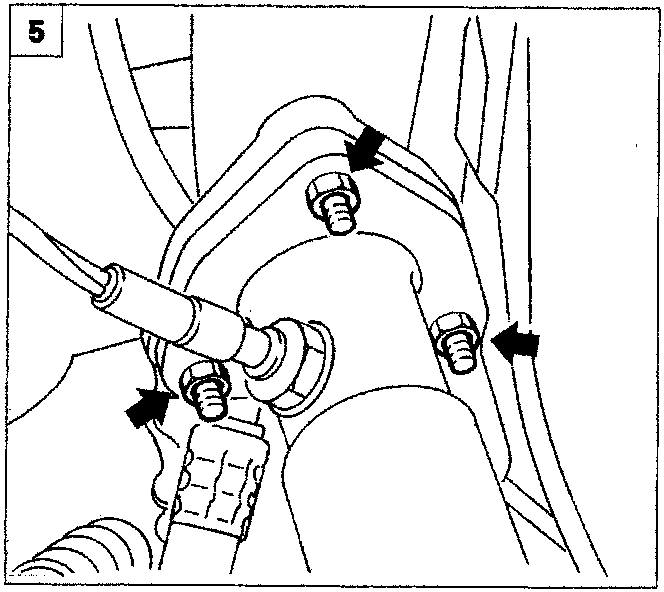
- Undo the nuts fixing the first section of the exhaust pipe to the exhaust manifold.
Parts & tools for this job For 1995 Fiat Bravo
- TOOLBattery testerSearch: car battery tester
- TOOLDigital multimeterSearch: automotive digital multimeter
- TOOLBattery terminal cleanerSearch: battery terminal cleaner
Links open Amazon search results in a new tab. As an Amazon Associate I earn from qualifying purchases.