
Wiring diagram of stalk unit
- Make
- Fiat
- Model
- Bravo /Brava (182) Factory Service Manual
- Year
- 1995–2001
- Section
- Various devices › Wiring diagram of stalk unit
55 Electrical systemWiring diagram of stalk unit
Wiring diagram of stalk unit
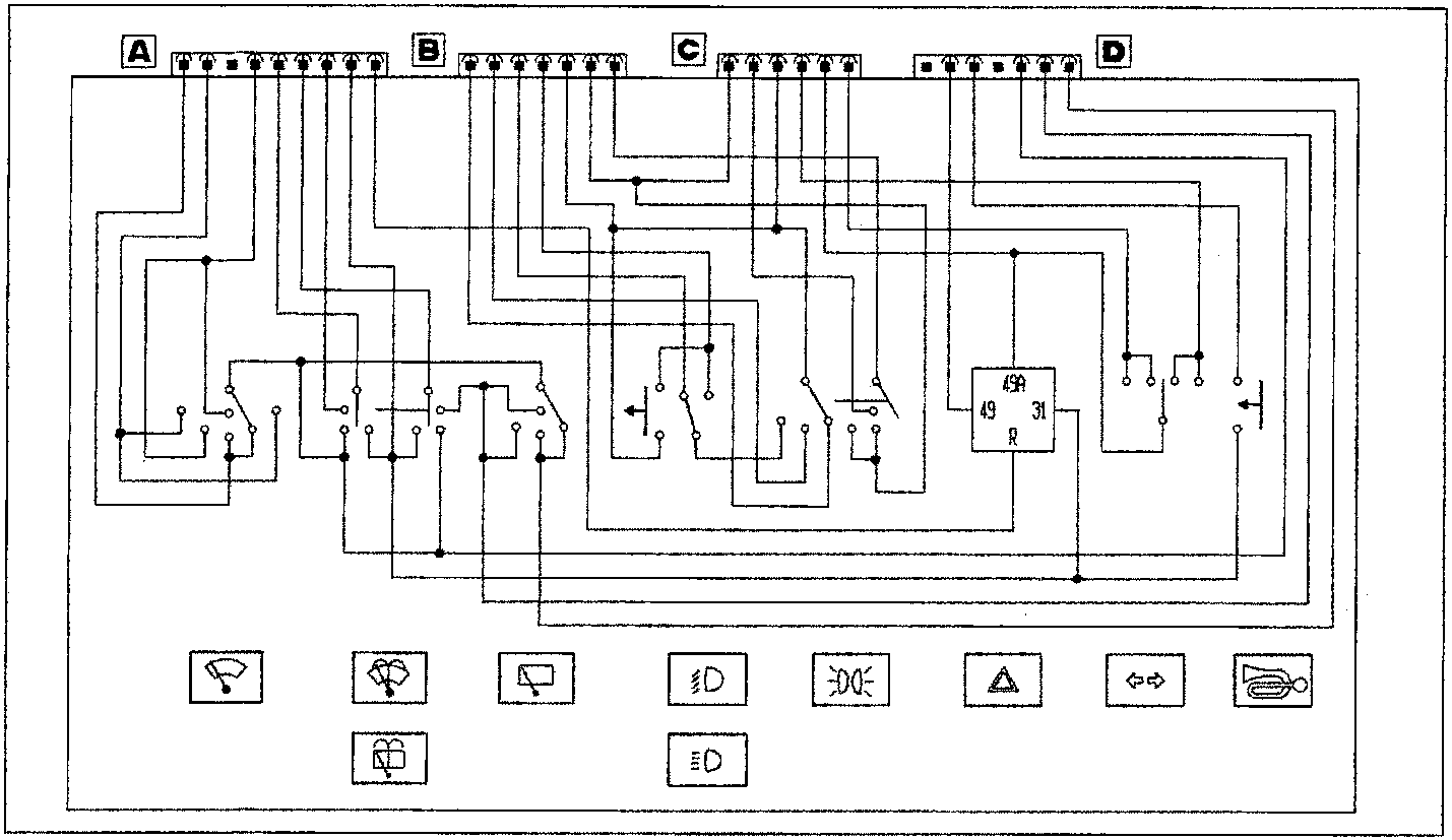
P4A038L01
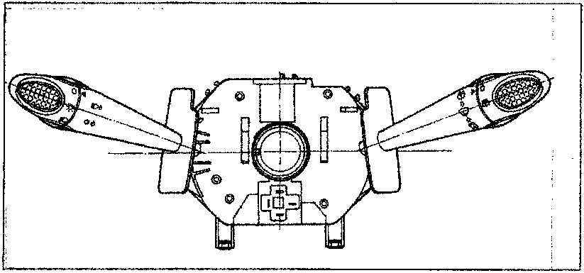
Front view of stalk unit
P4A038L02
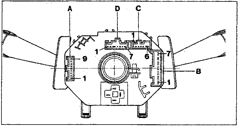
Rear view of stalk unit
P4A038L03
The letters indicate the sockets for the connectors of the corresponding names, and the numbers identify the relevant first and last pins.
Parts & tools for this job For 1995 Fiat Bravo
- TOOLDigital multimeterSearch: automotive digital multimeter
- PARTAssorted fuse kitSearch: car fuse assortment kit
- TOOLWire crimper and connector kitSearch: wire crimper connector kit
Links open Amazon search results in a new tab. As an Amazon Associate I earn from qualifying purchases.