
Introduction - gearbox
- Make
- Fiat
- Model
- Croma Factory Service Manual
- Year
- 2005–2010
- Section
- General › Introduction - gearbox
INTRODUCTION - GEARBOX
SPECIFICATIONS
The M32 manual gearbox is designed to be installed in front wheel drive systems with the engine tranversely mounted. The code M32 means that the gearbox has been designed to support a transmission with a maximum torque of 320 Nm.
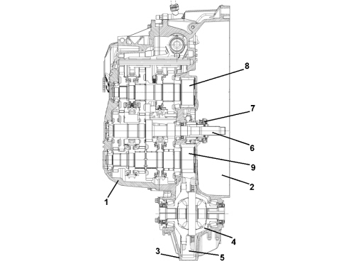
1. Gearbox casing
2. Clutch casing
3. Differential casing
4. Differential internal casing
5. Differential ring gear
6. Main shaft (A)
7. Clutch control coaxial actuator
8. Layshaft (B)
9. Second layshaft (C)
The specific features are:
- manual gearbox with fixed idler with six transmission ratios plus reverse;
- all gears with synchromesh (including reverse);
- toothed wheels with helical teeth;
- three shafts, one input plus two secondary (upper and lower);
- differential integrated in the gearbox casing;
- dry weight 46.7 km;
- activation by hydraulic clutch;
- designed for matching with twin mass flywheel;
- body divided into three sections to facilitate maintenance operations.
COMPOSITION OF THE GEARBOX
Inside the gearbox each transmission ratio is produced by means of a pair of gears that mesh constantly with one freewheeling on the respective shaft. Reverse gear is an exception and is produced by means of a train with three gears to reverse the direction of power.
The main shaft receives the drive directly from the crankshaft; when a gear is selected, the torque is transferred, via the pair of gears for the speed selected, to the layshaft and, from there, to the fixed idler, connected to the differential.
Engagement diagram
First and second speed
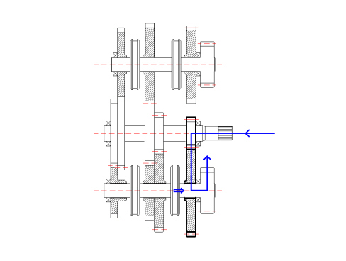
FIRST SPEED ENGAGEMENT
SECOND SPEED ENGAGEMENT
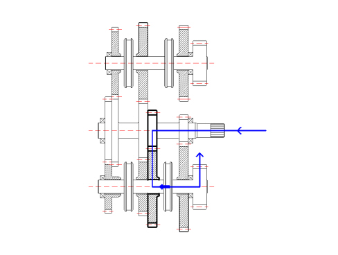
In first speed the power enters the gearbox via the main shaft and is transmitted, through the fixed drive gear, to the driven gear for the first speed fitted in neutral on the lower layshaft. The activation of the synchronizer (for first and second speed) makes the toothed wheel form one piece with the layshaft and, by means of the fixed idler wheel, with the differential.
By moving the synchronizer in the opposite direction, the driven gear for the second speed forms one piece with the layshaft; the second speed is produced in this way.
Third and fourth speed
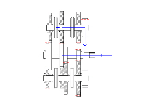
THIRD SPEED ENGAGEMENT
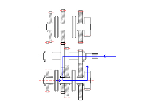
FIFTH SPEED ENGAGEMENT
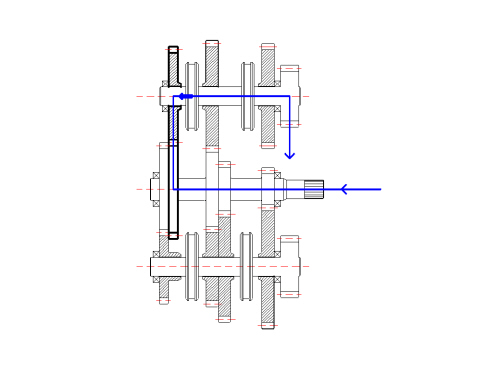
The power enters the gearbox via the main shaft and, by means of the fixed drive gear, is transferred to the driven gear, fitted on the upper layshaft; the activation of the synchronizer (for third and fourth speed) makes it possible to transfer the power to the toothed wheel for the fixed idler, also forming one piece with the differential ring gear, like the one on the lower shaft.
Moving the synchronizer in the opposite direction produces the engagement of fourth speed.
Fifth and sixth speed
FIFTH SPEED ENGAGEMENT
SIXTH SPEED ENGAGEMENT
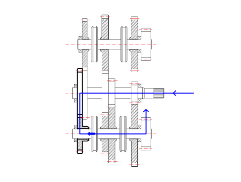
The power enters the gearbox via the main shaft and, by means of the fixed drive gear, is transferred to the driven gear, fitted on the lower layshaft; the activation of the synchronizer (for fifth and sixth speed) makes it possible to transfer the power to the toothed wheel for the fixed idler, also forming one piece with the differential ring gear.
To engage sixth speed, the same synchronizer is activated in the opposite direction to previously.
Reverse gear
REVERSE GEAR ENGAGEMENT
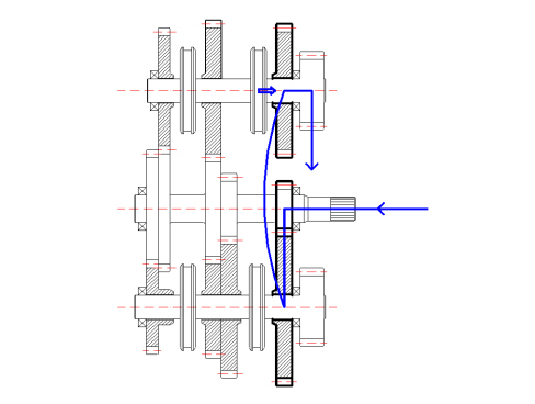
The power entering the gearbox is transferred from the main shaft to the gear for first speed fitted on the lower layshaft; this gear acts as a free wheel because it transfers the power to the toothed wheel for reverse gear fitted on the upper layshaft with which it meshes; at the same time, this allows the reversal of the power. The synchronizer for reverse gear makes the wheel form one piece with the upper layshaft, transferring the power to the differential.
Toothed wheels
MATERIALS AND MACHINING: the toothed wheels are subjected to variable loads over a period of time which produce stresses and fatigue; for these reasons nickel chrome steel alloys are used which afford good mechanical resistance; after machining the toothed wheels firstly undergo a finishing process (grinding) and afterwards a heat treatment that improves their resistance properties to fatigue and wear (binding and tempering).
SPECIFICATIONS: the toothed wheels used have helical teeth. The adoption of toothed wheels with helical teeth allows the transmission of higher torques compared with those of the same size with straight teeth; in addition, toothed wheels with helical teeth afford smoother and quieter operation; another important feature of the gears in the gearbox in question is the teeth with a high covering factor; several teeth (and not just one) are always meshed, with the advantage of smooth transmission.
Shafts
Main shaft (a)
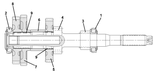
1. Front bearing
2. Rear bearing
3. 1st speed gear
4. 2nd speed gear
5. 3rd-5th speed gear
6. Spacer
7. 4th speed gear
8. 6th speed gear
9. Needle bearings
SPECIFICATIONS: the gearbox input shaft has all the toothed wheels forming one piece: in particular the toothed wheels for first and second are directly on the part, i.e. they physically form part of the shaft as they are produced through mechanical machining processes, whilst the others for third and fifth speeds and fourth and sixth are fitted by means of splining in the actual shaft and are an interference with on the shaft itself.
The gearbox main shaft is supported by two conical roller bearings.
Layshaft (b)
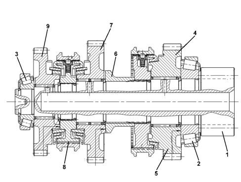
1. Pinion
2. Front bearing
3. Rear bearing
4. Reverse gear
5. Reverse single cone synchronizer
6. Spacer
7. 3rd speed gear
8. 3rd-4th speed double cone synchronizer
9. 4th speed gear
SPECIFICATIONS: the upper layshaft supports the wheels that produce third and fourth forward speeds and reverse; these wheels are all fitted in neutral on roller bearings.
There are two synchronizers: one, triple cone synchronizer, designated to form one piece between the wheels for third or fourth speed with the shaft, the other single cone synchronizer, for reverse.
There is a toothed wheel on the shaft that transfers the power to the differential ring gear.
The shaft is supported by two conical roller bearings.
Second layshaft (c)
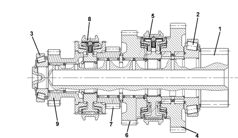
1. Pinion
2. Front bearing
3. Rear bearing
4. 1st speed gear
5. 1st-2nd speed triple cone synchronizer
6. 2nd speed gear
7. 5th speed gear
8. 5th-6th speed single cone synchronizer
9. 6th speed gear
The wheels that produce first, second, fifth and sixth forward speeds are fitted on this shaft; the toothed wheel for first speed is also involved in producing reverse.
The shaft is supported by two conical roller bearings.
Synchronizers
The diagram shows the exploded view of the synchronizer for third and fourth speeds. It is the triple cone type to ensure optimum continuity and smooth transfer of torque between the shafts.
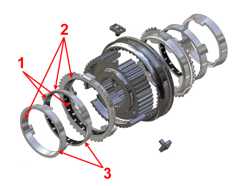
1. On the synchronizer for third and fourth speeds, two of the three cones contain a carbon friction ring
2. The synchronizer for first and second speeds also has this friction ring on all three cones.
3. The synchronizers for fifth and sixth speeds and reverse are the single cone type (they do not have the first two cones).
In the case of the synchronizer for fifth and sixth speeds and reverse, given the lesser torque produced by the actual gearbox, a single cone synchronizer is used.
Gear selector and engagement assembly
The gear selector and engagement assembly comprises a kinematic arrangement connected, by means of cables, to the control lever in the passenger compartment.
The kinematic arrangement has two possible movements: vertical travel designed to select the synchronizer; movement in a rotary direction is designed to activate the fork for the synchronizer.
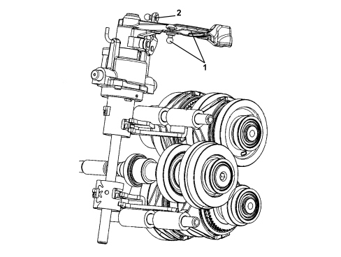
1. Gear engagement lever
2. Gear selection lever
SPECIFICATIONS
A new generation Getrag gearbox has been fitted on the 2.2 16v version.
The main features of the gearbox are:
- reduced axial size
- excellent manoeuvrability in all gears
- extremely quiet operation.
The gearbox configuration is tranverse with three shafts and an internal differential. There are HRC teeth for all the gears super finished after a thermal treatment.
The gearbox and clutch casings have been designed to produce the same resistance at minimum weight (FEM/FINITE ELEMENT METHOD).
The gears all have synchromesh including reverse and the synchronizer rings are all made from brass with a Borg Warner type molybdenum coating.
The first and second speed gears, including the synchronizer rings, are fitted on an idler shaft between the main shaft and the layshaft.
The gears and synchronizers for third and fourth speeds are located on the main shaft and for fifth and reverse on the layshaft.
For first and second speeds, the gears used the most, the synchronizer rings are the double cone type and ensure reduced engagement forces compared with traditional or single ring type synchronizers.
The internal gear control system is produced by means of three selection planes with a central gear positioner with a bearing.
The clutch is hydraulically operated with the C.S.C. system co-axial on the main shaft inside the gearbox.
The components inside the gearbox are lubricated dynamically, by means of the oil flowing through the ducts in the casings and the ports in the shafts as well as additional plastic ducts; all of this allows improved torque transmission and better protection against wear. This system has a device for the recovery of the clutch plate wear which allows the load on the clutch pedal to remain constant throughout the life of the vehicle
The advantages of this system lead to:
- improved acoustic comfort,
- reduction of the engagement force,
- no vibrations / shuddering of the lever.
TRANSMISSION OF POWER IN THE VARIOUS GEARS
First speed
The power enters from the main shaft, is transmitted to the intermediate shaft through the engagement of the 1st speed gear (assembled on the intermediate shaft).
The 3rd speed gear (assembled on the main shaft and in "neutral") allows the transmission of the power from the intermediate shaft to the layshaft and therefore to the differential thereby completing the kinematic chain for the first speed.
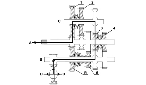
A - main shaft input
B - layshaft
C - intermediate shaft
D - differential output
Second speed
The power enters from the main shaft, is transmitted to the intermediate shaft through the engagement of the 2nd speed gear (assembled on the intermediate shaft).
The 3rd speed gear (assembled on the main shaft and in "neutral") allows the transmission of the power from the intermediate shaft to the layshaft and therefore to the differential thereby completing the kinematic chain for the second speed.
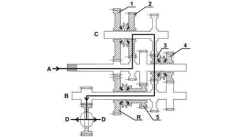
A - main shaft input
B - layshaft
C - intermediate shaft
D - differential output
Third speed
The drive that enters from the main shaft is transmitted directly to the layshaft and therefore to the differential through the engagement of the 3rd speed gears (assembled on the main shaft) producing the kinematic chain for the third speed.
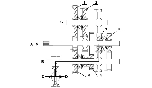
A - main shaft input
B - layshaft
C - intermediate shaft
D - differential output
Fifth speed
The drive that enters from the main shaft is transmitted directly to the layshaft and therefore to the differential through the engagement of the 4th speed gears (assembled on the main shaft) producing the kinematic chain for the fourth speed.
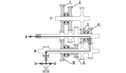
A - main shaft input
B - layshaft
C - intermediate shaft
D - differential output
Fifth speed
The drive that enters from the main shaft is transmitted directly to the layshaft and therefore to the differential through the engagement of the 5th speed gears (assembled on the layshaft) producing the kinematic chain for the fifth speed.
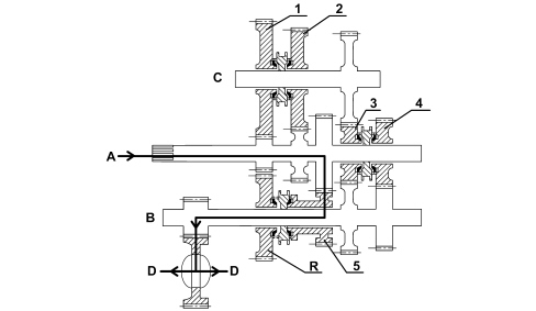
A - main shaft input
B - layshaft
C - intermediate shaft
D - differential output
Reverse gear
The drive entering from the main shaft is transmitted to the layshaft by means of the kinematic chain produced by the gear for the 1st speed (assembled on the intermediate shaft in in "neutral") and that for reverse gear (assembled on the layshaft) at the time the respective synchronizer is engaged.
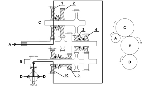
A - main shaft input
B - layshaft
C - intermediate shaft
D - differential output
Five speed transverse gearbox with three shafts supported by bearings with gears constantly engaged and final drive ratio.
The clutch engagement device is fitted on the main shaft.
The external controls have a twin cable.
CONSTRUCTION SPECIFICATIONS
The structure of the gearbox consists of: a gearbox casing containing the main and layshafts fitted in the special rear flange, the gear engagement forks and rods and the gear selector/engagement device.
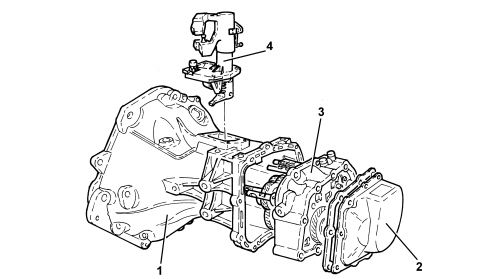
1. Gearbox casing
2. Cover
3. Rear flange
4. Gear selection-engagement device
MAIN SHAFT
The main shaft comprises gears directly on the shaft.
The main shaft is supported through a ball bearing fitted on the rear flange and a roller bearing on the gearbox casing.
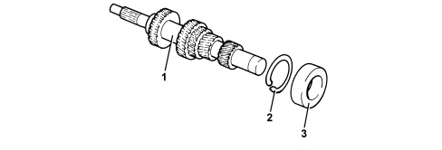
1. Main shaft
2. Circlip
3. Bearing (rear flange side)
LAYSHAFT
The layshaft comprises the 1st, 2nd, 3rd, 4th and 5th speed gears fitted on needle bearings with synchronizers.
The layshaft is supported through a ball bearing fitted on the rear flange and a roller bearing on the gearbox casing.
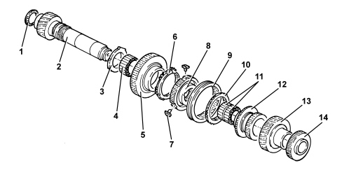
1. Support ring
2. Layshaft
3. Thrust collar
4. Needle bearing
5. Reverse driven gear
6. Reverse synchronizer
7. Pre-synchronizer mounting
8. Synchronizer hub
9. Synchronizer sleeve
10. Synchronizer ring
11. Needle bearings
12. 4th speed driven gear
13. 3rd speed driven gear
14. 5th speed driven gear
GEARS
The gears are the helical toothed type for the forward gears and straight toothed for reverse. The compactness of the synchronizers has made it possible to produce wider gears with a larger surface for the sides of the teeth which are quieter during rotation.
SYNCHRONIZERS
The synchromesh on all the forward gears (there is no synchromesh for reverse, but it is always engaged on the main shaft to reduce sticking during engagement) is the baulk ring type (Borg-Warner).
Pre-synchronizer mountings are used between the hub and the sleeve of each synchronizer unit to facilitate the operations of dismantling and reassembly.
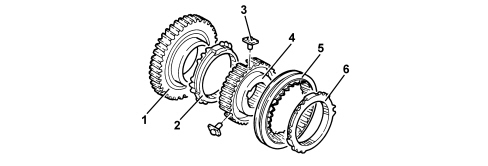
1. Gear
2. Synchronizer ring
3. Pre-synchronizer mounting
4. Synchronizer hub
5. Synchronizer sleeve
6. Synchronizer ring
DIFFERENTIAL
The differential comprises a crown wheel and pinion reduction and a differential casing in one piece that incorporates the planet and satellite gears. The differential casing is supported on two conical bearings.
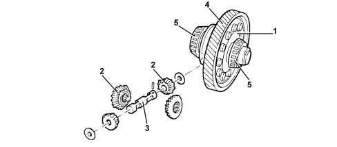
1. Differential casing
2. Planet/satellite gears
3. Manual gearbox satellite carrier with thrust washers
4. Ring gear
5. Conical bearings
Parts & tools for this job For 2005 Fiat Croma
- TOOLTorque wrenchSearch: 3/8 inch torque wrench
- TOOLSocket setSearch: socket set metric
- BOOKHaynes manualSearch: Haynes manual Fiat Croma
Links open Amazon search results in a new tab. As an Amazon Associate I earn from qualifying purchases.