
Introduction - steering
- Make
- Fiat
- Model
- Croma Factory Service Manual
- Year
- 2005–2010
- Section
- General › Introduction - steering
INTRODUCTION - STEERING
DESCRIPTION
The steering system consists of an electrohydraulic system known as EPHS (Electric Powered Hydraulic Steering system) that was created as a power saving application because the pump is operated by an electric motor, unlike a conventional hydraulic system where the hydraulic pump is driven directly by the engine.
In this system, it is possible to alter the speed of the brushless motor that operates the pump on the basis of vehicle speed and steering speed to activate the variable assistance function.
Its action varies according to vehicle speed and steering angle. The power assisted steering is programmed so that its effects decrease as the speed of the vehicle increases. In this way it is possible to turn the steering wheel with great ease whilst parking and maintain safe contact with the road whilst driving at high speed. In practice, the system varies the hydraulic assistance (pump rpm) according to the rotation speed of the steering and the speed of the vehicle thereby being able to produce greater assistance when parking and extremely low hydraulic assistance at speed.
The turning circle is 10.9 m.
Versions
The system is supplied in two mains versions known as “COMPACT” and “REMOTE”.
Compact version
The Compact system is fitted on the following engine versions:
-1.9 JTD 8V
-1.9 JTD 16V
-2.4 JTD
-1.8 16V
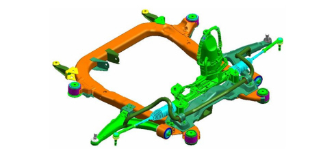
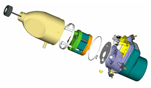
The Compact version is assembled on the vehicle as a single unit. The MPU (Motor Pump Unit) is fitted directly on the steering box. The hydraulic lines between the MPU and the steeing box are short and already assembled. The system is ready filled with fluid before delivery to the vehicle manufacturer.
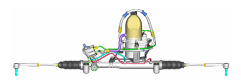
It is supplied with or without an SAS (Steering Angle Sensor) that is used to transmit the steering column rotation speed to the MPU (Motor Pump Unit).
The sensor is fitted to the steering in all versions that do not come with ESP as standard. On these versions, steering column rotation speed is sent to the MPU via a sensor directly connected to the steering column.
Remote system
The Remote system is fitted on the following engine versions:
- 2.2 MPI
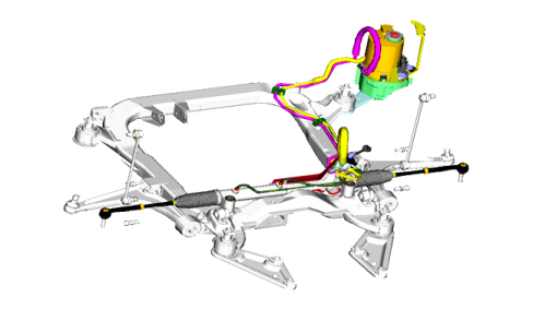
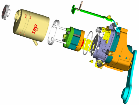
The componetns of the system (MPU, box and pipes) are assembled directly on the vehicle. After assembly on the vehicle, the system must be filled with fluid and bled.
The remote steering system is not fitted with an SAS sensor. All engines that use this system are fitted with an ESP as standard and use a steering angle sensor on the stalk unit.
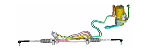
COMPONENTS
Electric pump
Compact version:
the electrohydraulic steering fluid reservoir is positioned inside the engine compartment. The level must correspond to the MAX reference mark on the dipstick integral with the fuel cap.
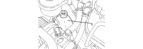
1. Electrohydraulic steering fluid reservoir
Remote version:
the reservoir is located behind the right front headlamp. Remove the wheel guard to check the level.
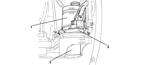
1. Electrohydraulic steering fluid reservoir
2. Electrohydraulic steering control electronic control unit
3. Pump unit
Steering box
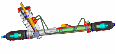
The technical specifications of the steering box are as follows:
- max hydraulic pressure: 10.7 ± 0.4 MPa
- fluid temperature: 120°C
- steering box ratio: 52.3 mm/rev;
- ratio between steering wheel angle/wheel angle 15.2°steering wheel/°wheel;
- steering wheel revolutions 2.88 for one rack travel;
- total rack travel: 142.1 - 146.2 mm;
- turning circle: 10.9 m.
Steering column
The mechanical part of the mechanical steering column is telescopic and consists of two sections.
It makes a crucial contribution to preventing the steering wheel from moving back dangerously during frontal impact.
The lower section includes a sliding sleeve to maintain the steering wheel position fixed during impact. The max sliding load of 8 kg is achieved by means of an injected polyamide insert.
The upper section, added to allow the steering wheel position to be adjusted, is:
- sliding for axial adjustment;
- swivelling for vertical adjustment.
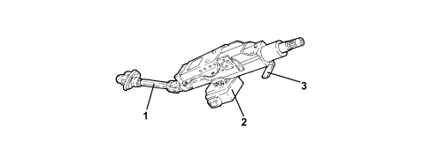
1. Sliding sleeve
2. Electromechanical steering lock engagement device
3. Steering wheel position adjustment lever
The steering column is supported by a steel mount in turn secured to a steel bracket. The stiffness of these components contributes signficantly to minimising steering wheel vibrations.
All this allows the following objectives to be achieved:
- vehicle passive safety;
- driving comfort.
Steering lock
The steering lock system is the friction type as required by current European legislation on theft prevention. A metal key integral with the NBS body slides in a groove of the friction bush applied to the upper steering column.
The friction system is on the upper shaft by the ignition and consists of:
- friction bush;
- Rencol Ring.
The smooth part allows sliding rotation for torque values between 100 and 240 Nm.
By limiting the maximum transmissible torque, the clutch function of the friction system allows the following in the event of a theft attempt:
- the security of the steering column;
- the impossibility of breaking the lock mechanism.
Sas sensor
The SAS is an electronic instrument that transmits the steering speed to the pump unit. It is therefore supplied with the electrohydraulic unit on all Compact systems fitted to specifications not fitted with an ESP as standard. Versions fitted with an ESP system are fitted with a Steering Angle Node (NAS) that contains a sensor. This is fitted on the stalk unit clockspring.
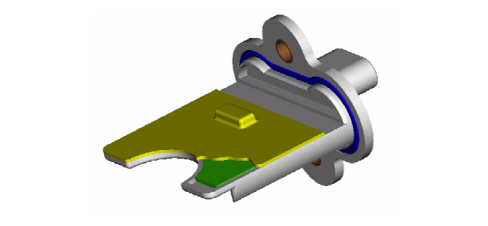
OPERATION
The sensor measures steering column rotation speed via its internal electronic system.
The sensor has an autodiagnostic function and is capable of carrying out a check on the plausibility of the information processed.
Control unit
The control unit is integral with the pump case.
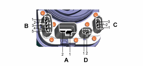
Power connector (Battery +, Battery -)
| Power connector A | Signal |
|---|---|
| Pin 1 | + 12V battery |
| Pin 2 | Earth |
Other signals:
| Connector B | Signal |
|---|---|
| Pin 1 | Ignition (IGN, +15) |
| Pin 2 | CAN_H |
| Pin 3 | CAN_L |
| Pin 4 | CAN_H |
| Pin 5 | CAN_L |
| Connector C | Signal |
|---|---|
| Pin 1 | SRS Positive SAS |
| Pin 2 | SRS Negative Earth SAS |
| Pin 3 | SRS Signal SAS |
| Connector D | Signal |
|---|---|
| Pin 1 | N.C. |
| Pin 2 | K line |
Parts & tools for this job For 2005 Fiat Croma
- TOOLTie rod end toolSearch: tie rod end puller
- TOOLBall joint separatorSearch: ball joint separator
- FLUIDPower steering fluidSearch: Fiat power steering fluid
Links open Amazon search results in a new tab. As an Amazon Associate I earn from qualifying purchases.