
Single cylinder head extension - change gasket
- Make
- Fiat
- Model
- Doblò Factory Service Manual
- Year
- 2000–2010
- Section
- Cylinder head – s › Single cylinder head extension - change gasket
Single cylinder head extension - change gasket
Removing
Position the car on the ramp.
Ensure that the ignition key is in the OFF position, then disconnect the negative battery terminal.
| Name | Connector | |
|---|---|---|
| Battery | A1 |
Carry out - 0010T84 coolant for air conditioning system dehydrate and recharge
Carry out - 5530B10 battery - r+r
Carry out - 5530B52 Battery DRIP TRAY/SUPPORT - R.R.
Carry out - 1060G90 diesel injection wiring harness - r r
Carry out - 4450B04 right front wheel r r
Carry out - 7055B54 under-engine guard - r r
Undo the fuel filler cap and remove it to discharge the pressure in the system.
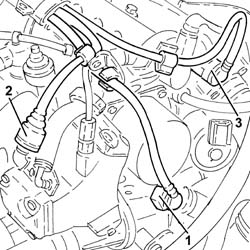
1. Disconnect the quick-release fitting of the coolant return pipe to the engine coolant reservoir, thermostat side.
Undo the fuel filler cap and remove it to discharge the pressure in the system.
2. Disconnect the rapid connector for the fuel supply pipe from the fuel filter to the pressure pump, pressure pump side.
3. Disconnect the rapid attachment for the fuel return pipe to the tank, single fuel manifold pipe side.
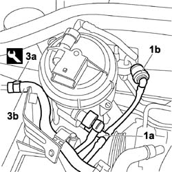
1. Working on the rapid connectors (1a) and (1b), disconnect the fuel return pipe. Seal the ends.
2. Working on the rapid connector, disconnect the fuel supply pipe. Seal the ends.
3. Using the special tool, loosen the band (3a) and disconnect the engine coolant return pipe (3b). Seal the ends.
| Name | Country | |
|---|---|---|
| 3a | Pliers | 1.881.138.000 |
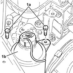
1. Undo the fixing bolts (1a) and move the power assisted steering fluid reservoir (1b) aside.
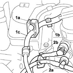
1. Release the engine coolant return pipe (1c) from the securing clips (1a) and (1b).
2. Release the fuel supply and return pipes (2a) from the securing clips (2b).
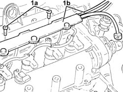
Undo the fixing bolts (1a) and remove the pipe retaining duct (1b) from the engine.
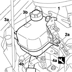
1. Using a suitable size plug (1a) to ensure the seal, seal the end in the engine coolant reservoir (1b).
2. Undo the fixing bolt (2a) and remove the mounting bracket (2b).
3. Undo the bolts (3a) and detach the engine coolant expansion tank (3b).
4. Using the special tool, loosen the band (4a) and disconnect the engine coolant return pipe (4b) and seal the end.
| Name | Country | |
|---|---|---|
| 4a | Pliers | 1.881.138.000 |
Carry out - 1008B10 power unit front mount (timing side) flexible block - replace /p>
Carry out - 1008A46 cam shaft left rigid mount - r r
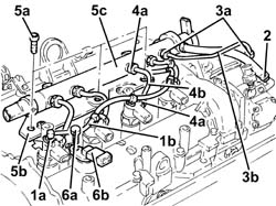
1. Manually push the clips (1a) and disconnect the return pipe from the injectors to the manifold (1b), injectors side.
2. Loosen the band and disconnect the fuel return pipe from the pressure pump, pressure pump side.
3. Undo the connectors (3a) and remove the pipe from the pressure pump to the fuel manifold (3b).
When refitting, fit a new pipe from the pressure pump to the fuel manifold.
4. Undo the connectors (4a) and remove the pipe from the fuel manifold to the injectors (4b).
Use new pipes from from fuel manifold to injectors upon reassembly.
5. Undo the bolts (5a) and remove the mounting brackets (5b) complete with single fuel manifold pipe (5c).
6. Undo the bolt (6a) and remove the cam angle sensor (6b).
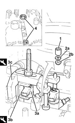
1. Undo the injector mounting bracket nut.
2. Remove the washer (2a) and tapered washer (2b).
3. Fit the injectors (3a), one at a time, using tools (3b) and (3c).
If the same injectors are being reused, mark the cylinder to which they belong so that they can be correctly refitted.
If new fuel injector(s) are fitted, the self-learning procedure with the Examiner must be carried out.
| Name | Country | |
|---|---|---|
| 3b | Extractor | 1.870.900.700 |
| Name | Country | |
|---|---|---|
| 3c | Extractor | 1.870.739.000 |
Remove the fuel injectors complete with bracket.
Repeat the above procedure to remove the remaining pair of injectors.
4. Remove the injector seals from the single camshaft housing.
These seals are replaced each time they are refitted.
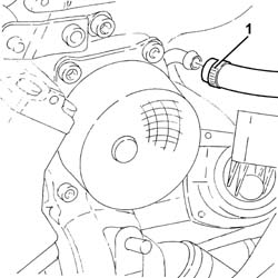
1. Loosen the band and disconnect the brake servo vacuum pipe, vacuum unit side.
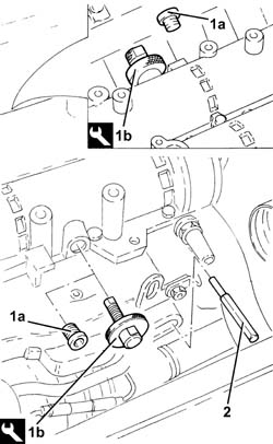
1. Remove the caps (1a) and fit the tools (1b) on the camshafts in their place.
Fit the tool positioning it with the millings in a horizontal position and checking that it is correctly inserted in the housings in the camshafts.
| Name | Country | |
|---|---|---|
| 1b | Template | 1.871.000.900 |
2. Fit a suitable (8 mm diameter) pin via the special opening in the gearbox.
Check that the pin is correctly inserted in the housing in the engine flywheel.
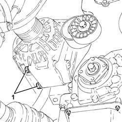
1. Loosen the lower bolts fixing the alternator to the mounting.
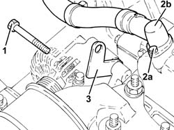
1. Undo the upper bolt fixing the alternator to the mounting.
2. Undo the bolt (2a) and disconnect the connector (2b) for the engine oil vapour recovery pipe from the timing cover with the chain drive.
3. Fit a suitable bracket for supporting the power unit and secure it using the upper alternator fixing bolt to the mounting.
Tighten the lower bolts fixing the alternator to the mounting.
1. Fit the tool (1a), complete with support mountings (1b).
| Name | Country | |
|---|---|---|
| 1 | Crossmember | 1.870.595.000 |
| Name | Country | |
|---|---|---|
| Support mountings | 1.870.650.000 |
2. Connect the rod to the bracket fitted previously on the alternator mounting.
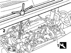
Carry out - 1092C10 power steering and/or self-levelling suspension pump drive belt - r + r
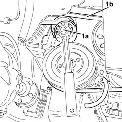
1. Use a spanner on the moving tensioner (1a) and remove the engine components single drive belt (1b).
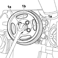
1. Stop the rotation of the crankshaft using a suitable spanner, undo the bolts (1a) and remove the services pulley (1b).
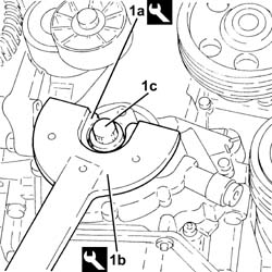
1. Using the tools (1a) and (1b) for counter-torque, loosen the left hand thread bolt (1c) fastening the pulley support flange to the crankshaft.
| Name | Country | |
|---|---|---|
| 1a | Counter-torque | 1.871.000.200 |
| Name | Country | |
|---|---|---|
| 1b | Support for counter-torque | 1.860.831.000 |
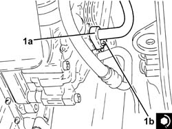
1. Undo the bolt (1a) and disconnect the pipe from the expansion valve to the compressor (1b), compressor side.
Seal the disconnected connectors, using suitable plugs, to prevent humidity and impurities from entering the system.
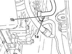
Carry out - 1008B10 power unit front mount (timing side) flexible block - replace
Carry out - 1092C14 power steering pump/self levelling suspension pump pulley - r + r with belt removed
Carry out - 1008A46 cam shaft left rigid mount - r r
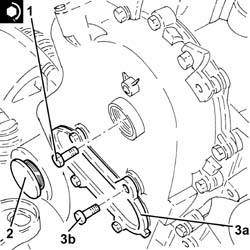
1. Undo the plug (1a) and the bolt (1b) fixing the exhaust side camshaft toothed drive pulley.
2. Undo the bolts (2a) and remove the cover (2b) complete with gasket.
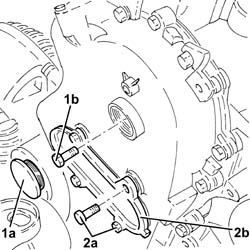
Release the toothed pulley from the exhaust side camshaft working via the opening in the timing cover adjusting it on the inner rib of the timing cover.
After this operation the piston for the timing moving tensioner should be fully removed.
1. Undo the bolts fixing the timing cover to the single camshaft housing.
2. Keep the brackets
3. Undo the bolts (3a) and (3b), then remove the single camshaft housing assembly (3c).
4. Remove the single camshaft housing gasket.
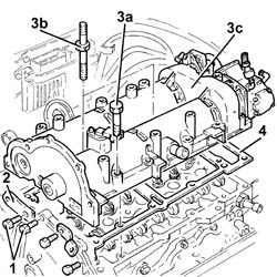
Refitting
1. Apply Fiat silicon sealant 71713687 or a similar product to the contact area between the cylinder head and the timing chain cover.
2. Position the gasket (2a) on the cylinder head, fitting it on the centring bushes (2b).
3. Apply Fiat silicone sealant 71713687 or a similar product to the gasket between the lower cylinder head and the camshaft housing to the area in contact with the timing cover.
4. Also apply the same sealant to the surface of the timing cover gasket, following the black silicone line on the actual gasket.
Apply a thin layer of sealant to the timing cover gasket so that it is not too thick and to prevent excess sealant going inside the timing cover.
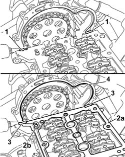
Working with the camshaft timing tools fitted, position the single camshaft housing taking care not to move the rockers from their position.
Screw in the bolts fixing the single camshaft housing to the cylinder head without tightening them.
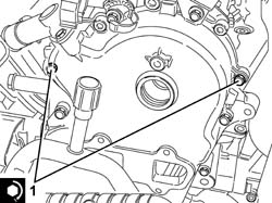
1. Screw in and tighten the bolts shown fixing the timing cover to the single camshaft housing to torque.
During this stage, do not tighten the remining timing cover fixing bolts.
| Fastening | Component | Ø | Value (daNm) | |
|---|---|---|---|---|
| 1 | Bolt | TIMING COVER | M6 | 0.8 ÷ 1.0 |
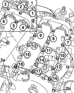
1. Tighten the six rear bolts fixing the single camshaft housing to a torque of 0.9 daNm.
2. Loosen the bolts (2a) and (2b) fixing the timing cover tightened previously.
3. Continue tightening the bolts fixing the camshaft housing to a torque of 0.9 daNm following the order illustrated in the diagram gradually working towards the timing cover.
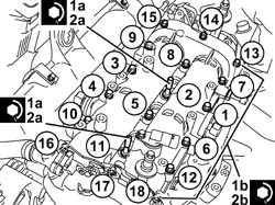
1. Tighten the bolts fixing the single camshaft housing M8 (1a) to a pre-torque of 1.5 daNm and M7 (1b) to a pre-torque of 1.2 daNm.
2. Tighten the bolts (2a) and (2b) fixing the single camshaft housing to the recommended torque.
Follow the order shown in the diagram for each tightening sequence.
| Fastening | Component | Ø | Value (daNm) | |
|---|---|---|---|---|
| 2a | Bolt | CYLINDER HEAD EXTENSION | M8 | (Lower cylinder head side) 2.5 |
| Fastening | Component | Ø | Value (daNm) | |
|---|---|---|---|---|
| 2b | Bolt | CYLINDER HEAD EXTENSION | M7 | (Lower cylinder head side) 1.8 |
Fit the remaining bolts fixing the timing cover to the single camshaft housing, then tighten all the bolts fixing the timing cover to the single camshaft housing to the recommended torque.
| Fastening | Component | Ø | Value (daNm) | |
|---|---|---|---|---|
| Bolt | TIMING COVER | M6 | 0.8 ÷ 1.0 |
The single camshaft housing - cylinder head non alignment should not exceed the recommended value.
Only the camshaft housing may project.
| Measurement | Value | ||
|---|---|---|---|
| Upper cylinder head - cylinder head misalignment (mm) | 0.1 |
1. Fasten the tool to the timing cover by the inspection opening so that the pin is in the moving plate rib; using the tool lever, retract the chain tensioner piston so that it is locked.
| Name | Country | |
|---|---|---|
| 1 | Lever | 1.870.900.400 |
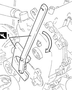
Fit the toothed pulley on the exhaust side camshaft working via the opening in the timing cover.
Position the bolt fixing the gear and screw it in without tightening it to prevent the gear from being able to accidentally come out of the housing.
Using the tool lever, fully retract the chain tensioner piston to allow the inner spring to be reloaded and ensure that the timing chain tension is correct.
Release the chain tensioner piston checking that it is in contact with the moving plate.
Remove the tool.
| Name | Country | |
|---|---|---|
| Lever | 1.870.900.400 |
1. Using the camshaft timing tools fitted previously, tighten the exhaust side camshaft toothed drive pulley fixing bolt to the recommended torque.
| Fastening | Component | Ø | Value (daNm) | |
|---|---|---|---|---|
| 1 | Bolt | TIMING DUCT PULLEY | M12 | (Exhaust camshaft side) 10.8 ÷ 13.2 |
2. Tighten the plug.
3. Place the tapper cover (3a), complete with gasket, back in its housing and fix it using the bolts (3b).
Carry out - 1008A46 cam shaft left rigid mount - r r
Carry out - 1092C14 power steering pump/self levelling suspension pump pulley - r + r with belt removed
Carry out - 1008B10 power unit front mount (timing side) flexible block - replace
Place the engine coolant reservoir in position and secure it using the nuts.
Tighten the fixing nut and fit the wiring mounting bracket.
Connec the system supply pipe, radiator side.
1. Connect the pipe from expansion valve to compressor (1b), compressor side and tighten the bolt (1b) to the recommended torque.
Replace the O-rings for the connectors using green coloured seals only, resistant to R134a refrigerant fluid.
Lubricate the thread of the connectors using anti-freeze..
| Fastening | Component | Ø | Value (daNm) | |
|---|---|---|---|---|
| 1b | Bolt | EXPANSION VALVE - COMPRESSOR PIPE | M6 | (Compressor side) 0.7 ÷ 1.1 |
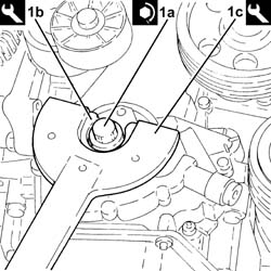
1. Tighten the left hand bolt (1a) fixing the pulley support flange to the crankshaft to the recommended torque using tools (1b) and (1c) for counter-torque.
| Fastening | Component | Ø | Value (daNm) | |
|---|---|---|---|---|
| 1a | Left hand thread bolt | PULLEY SUPPORT FLANGE ON CRANKSHAFT | M14 | (Crankshaft side) 21.9 ÷ 24.2 |
| Name | Country | |
|---|---|---|
| 1b | Counter-torque | 1.871.000.200 |
| Name | Country | |
|---|---|---|
| 1c | Support for counter-torque | 1.860.831.000 |
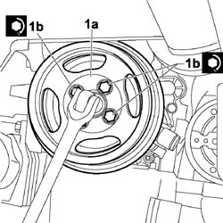
Place the crankshaft pulley (1a) in its housing and tighten the fixing bolts (1b). Stop the rotation of the crankshaft using a suitable spanner and tighten to the recommended torque.
| Fastening | Component | Ø | Value (daNm) | |
|---|---|---|---|---|
| 1b | Bolt | CRANKSHAFT PULLEY | M8 | (Timing side) 2.3 ÷ 2.8 |
Adjust the moving tensioner and fit the engine components single drive belt using a spanner.
Carry out - 1092C10 power steering and/or self-levelling suspension pump drive belt - r + r
Remove the safety tools used for supporting the power unit.
| Name | Country | |
|---|---|---|
| Crossmember | 1.860.851.000 |
| Name | Country | |
|---|---|---|
| Vertical support | 1.871.001.300 |
| Name | Country | |
|---|---|---|
| Crossmember | 1.870.595.000 |
| Name | Country | |
|---|---|---|
| Support mountings | 1.870.650.000 |
Undo the upper bolt, loosen the lower bolts fixing the alternator and remove the bracket used for supporting the power unit.
Tighten the bolts fixing the alternator to the mounting to the recommended torque.
| Fastening | Component | Ø | Value (daNm) | |
|---|---|---|---|---|
| Bolt | ALTERNATOR ASSEMBLY | M8 | (Support side) 2.3 ÷ 2.8 |
Connect the connector for the engine oil vapour recovery pipe to the chain drive timing cover and tighten the bolt.
Make sure that the O-Ring is correctly positioned.
Remove the pin from the hole on the gearbox.
Remove the timing tools from the camshafts and tighten the plugs.
| Name | Country | |
|---|---|---|
| Gauge | 1.870.896.900 |
Connect the brake servo vacuum intake pipe, vacuum unit side and tighten the band.
Place the new injector seals in their housings in the single camshaft housing.
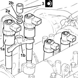
1. Place the injectors (1a), complete with brackets (1b), in their seats.
Before refitting, replace the copper seal on the injectors.
2. Refit in their seatings the tapered washer (2a) and washer (2b).
3. Tighten the nut fixing the injector mounting bracket to the recommended torque.
| Fastening | Component | Ø | Value (daNm) | |
|---|---|---|---|---|
| 3 | Nut | INJECTORS(DIESEL) | M8 | (Cylinder head side) 1.8 ÷ 2.2 |
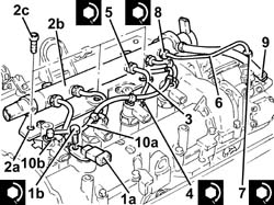
1. Plact the cam angle sensor (1a) back in its housing and secure it tightening the bolt (1b) to the recommended torque.
| Fastening | Component | Ø | Value (daNm) | |
|---|---|---|---|---|
| 1b | Bolt | CAM ANGLE SENSOR | M6 | (Cylinder head side) 0.6 ÷ 0.8 |
2. Place the mounting brackets (2a), complete with single fuel manifold pipe (2b), in their housings and fasten them using the bolts (2c).
3. Fit the new pipes from the fuel manifold to the injectors and secure them using the connectors without tightening them.
4. Tighten the connectors for the pipes from the fuel manifold to the injectors, injector side, to the recommended torque using a suitable spanner.
| Fastening | Component | Ø | Value (daNm) | |
|---|---|---|---|---|
| 4 | Connector | FUEL MANIFOLD LINE TO INJECTORS | M12 | (Injector side) 2.3 ÷ 2.5 |
5. Tighten the connectors for the pipes between the fuel manifold and the injectors, fuel manifold side, to the recommended torque using a suitable spanner.
| Fastening | Component | Ø | Value (daNm) | |
|---|---|---|---|---|
| 5 | Connector | FUEL MANIFOLD LINE TO INJECTORS | M14 | (Fuel manifold side) 2.7 ÷ 2.9 |
Clean the threaded seats for the above-mentioned pipe on the manifold and the injectors using heptane.
6. Place the pipe from the pressure pump to the single fuel manifold back in its housing and fix it using the connectors without tightening them.
7. Tighten the connector for the pipe from the pressure pump to the single fuel manifold, pump side, to the recommended torque using a suitable spanner.
| Fastening | Component | Ø | Value (daNm) | |
|---|---|---|---|---|
| 7 | Connector | PRESSURE PUMP LINE TO FUEL MANIFOLD | M12 | (Pressure pump side) 2.3 ÷ 2.5 |
8. Tighten the connector for the pipe from the pressure pump to the single fuel manifold, fuel manifold side, to the recommended torque using a suitable spanner.
| Fastening | Component | Ø | Value (daNm) | |
|---|---|---|---|---|
| 8 | Connector | PRESSURE PUMP LINE TO FUEL MANIFOLD | M14 | (Fuel manifold side) 2.7 ÷ 2.9 |
9. Connect the fuel return pipe from the pressure pump, pressure pump side, and tighten the band.
10. Connect the fuel outlet pipe from the injectors (10a), injector side pushing it until the clips (10b) can be heard clicking..
Place the pipe assembly in its housing and secure it using the bolts and bands.
Fasten the fuel supply and return pipes to the securing clips.
Carry out - 1008A42 gear box left rigid mount - r r.
Carry out - 1008B10 power unit front mount (timing side) flexible block - replace.
Connect the rapid connector for the intermediate coupling for the tank fuel return pipe.
Connect the rapid connector for the fuel return pipe, fuel filter side.
Connect the rapid connector for the fuel supply pipe from the filter to the pressure pump, fuel filter side.
Connect the engine coolant return pipe to the supply reservoir, reservoir side and tighten the band.
Connect the rapid attachment for the fuel return pipe to the tank, fuel single fuel manifold pipe side.
Connect the rapid connector for the fuel supply pipe from the filter to the pressure pump, pressure pump side.
Connect the quick-release fitting on the coolant return pipe to the engine coolant reservoir, thermostat side.
Carry out - 1060G90 diesel injection wiring harness - r r.
Carry out - 5530B52 Battery DRIP TRAY/SUPPORT - R.R..
Carry out - 5530B10 battery - r+r.
Carry out.
Carry out - 7055B54 under-engine guard - r r.
Carry out - 4450B04 right front wheel r r.
Fill the air conditioner coolant circuit - 0010T84 coolant for air conditioning system dehydrate and recharge.
Connect the battery negative terminal.
| Name | Connector | |
|---|---|---|
| Battery | A1 |
Remove the car from the ramps.
Parts & tools for this job For 2000 Fiat Doblò
- PARTEngine gasket setSearch: Fiat Doblò 2000 engine gasket set
- TOOLTorque wrenchSearch: 3/8 inch torque wrench
- TOOLFeeler gauge setSearch: feeler gauge set
Links open Amazon search results in a new tab. As an Amazon Associate I earn from qualifying purchases.