
Power steering pump r r
- Make
- Fiat
- Model
- Doblò Factory Service Manual
- Year
- 2000–2010
- Section
- Power steering › Power steering pump r r
Power steering pump r r
Removing
Position the vehicle on the lift.
Disconnect the negative battery lead.
Op. 4450B04 RIGHT FRONT WHEEL - R.R..
Op. 7055B54 PROTECTION/GUARD UNDER ENGINE - R.R..
Op. 1092C10 POWER STEERING AND/OR SELF-LEVELLING SUSPENSION PUMP DRIVE BELT - R + R.
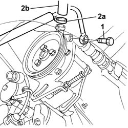
1. Disconnect the fitting connecting the high pressure pipe carrying fluid from the power steering pump to the casing.
Position a container beneath the vehicle and drain the fluid.
2. Disconnect the retaining band (2a) for the fluid inlet pipe (2b) from the reservoir on the pump.
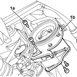
1. Unscrew bolts (1a) securing power steering pump (1b) (loosened previously) and remove complete with the bracket.
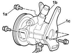
1. At the bench, undo the bolts (1a) fixing power steering pump (1b) to bracket (1c).
Refitting
Fit the power steering pump to the bracket at the bench and secure by means of retaining bolts.
| Fastening | Component | dia | Value (daNm) | |
|---|---|---|---|---|
| Bolt | POWER STEERING PUMP | M8 X 1.25 | 2.2 |
Position the power steering pump on the vehicle.
Tighten the bolts securing the power steering pump mount to the engine.
| Fastening | Component | dia | Value (daNm) | |
|---|---|---|---|---|
| Bolt | POWER STEERING PUMP SUPPORT/BRACKET | M10 X 1.25 | 5 |
Position the power steering pump belt on the drive pulley.
Fit the case protecting the drive belt on the power steering pump.
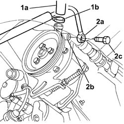
1. Connect the pipe carrying fluid (1a) from the reservoir to the power steering pump and secure it by means of collar (1b).
2. Connect fitting (2a) of high pressure pipe (2b) carrying fluid to the steering box to the pump and secure using bolt (2c).
| Fastening | Component | dia | Value (daNm) | |
|---|---|---|---|---|
| 2c | Connector | PIPE BTWN PUMP + POWER STEERING BOX | M16 X 1.5 | 4 |
Op. 1092C10 POWER STEERING AND/OR SELF-LEVELLING SUSPENSION PUMP DRIVE BELT - R + R.
Op. 7055B54 PROTECTION/GUARD UNDER ENGINE - R.R..
Op. 4450B04 RIGHT FRONT WHEEL - R.R..
Connect the negative battery lead.
Refill the power assisted steering system using the appropriate fluid.
| Type | Component | Description | Qty. | |
|---|---|---|---|---|
| Oil [l] | POWER ASSISTED STEERING CIRCUIT | TUTELA GI/A |
The use of TUTELA HP 20 power assisted steering fluid is recommended for use in particularly harsh climatic conditions
| Type | Component | Description | Qty. | |
|---|---|---|---|---|
| Oil [l] | POWER ASSISTED STEERING CIRCUIT | TUTELA HP 20 |
The power assisted steering system is self-bleeding; this is done by steering completely to the right and the left with the engine running and the vehicle stationary.
After bleeding the air, check the power steering fluid level again and top up if necessary.
Removing
Position the vehicle on a lift.
Disconnect the negative battery terminal.
| Description | Connector | |
|---|---|---|
| Battery | See A001 BATTERY |
Op. 1092C13 POWER STEERING PUMP DRIVE GUARD -ARRANGE
Op. 1092C10 POWER STEERING AND/OR SELF-LEVELLING SUSPENSION PUMP DRIVE BELT - R + R
Op. 1092C14 POWER STEERING PUMP/SELF LEVELLING SUSPENSION PUMP PULLEY - R + R WITH BELT REMOVED
Discharge the fuel pressure with the tool connected to the valve on the single fuel manifold pipe.
| Description | Code | |
|---|---|---|
| Rapid attachment connector | 1.870.684.000 |
1. Disconnect the fuel supply pipe from the rapid connector.
2. Disconnect the fuel vapour recovery pipe.
3. Disconnect the electrical connection for the fuel vapour recovery solenoid valve.
| Description | Connector | |
|---|---|---|
| 3 | Fuel vapour recovery solenoid valve | See L10 FUEL VAPOUR RECOVERY SOLENOID VALVE ( ENGINE ) |
4. Open the collar and move the pipes disconnected previously aside.
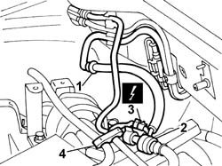
1. Position a FACOM DM.91 terminal (1a) or similar on the power steering fluid inlet pipe (1b) from the reservoir in order to prevent power steering fluid emerging from the pipe.
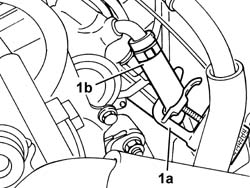
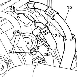
1. Unscrew fitting (1a) on power steering fluid pressurisation pipe (1b), then recover any power steering fluid that emerges in a suitable container.
2. Open collar (2a) and disconnect power steering fluid inlet pipe (2b) from the reservoir.
3. Undo the bolts (3a) and remove the power steeing pump (3b) from the engine compartment.
Refitting
Position the power steering pump on the mount.
Tighten the power steering pump bolts on the bracket to the specified torque.
| Fastening | Component | dia | Value (daNm) | |
|---|---|---|---|---|
| Bolt | POWER STEERING PUMP | M8 | 2.5 |
Connect the power steering fluid inlet pipe to the pump from the reservoir and close the retaining band.
Tighten the power steering fluid delivery pipe fitting to the pump to torque.
| Fastening | Component | dia | Value (daNm) | |
|---|---|---|---|---|
| Connector | POWER STEERING PUMP | M16 X 1.5 | 4 |
Remove the terminal positioned during removal of the power steering inlet pipe from the reservoir.
Connect the electrical connection for the fuel vapour recovery solenoid valve.
| Description | Connector | |
|---|---|---|
| Fuel vapour recovery solenoid valve | See L10 FUEL VAPOUR RECOVERY SOLENOID VALVE ( ENGINE ) |
Connect the fuel vapour recovery pipe.
Connect the fuel supply pipe rapid connector.
Re-close the pipe retaining band.
Op. 1092C14 POWER STEERING PUMP/SELF LEVELLING SUSPENSION PUMP PULLEY - R + R WITH BELT REMOVED
Op. 1092C10 POWER STEERING AND/OR SELF-LEVELLING SUSPENSION PUMP DRIVE BELT - R + R
Op. 1092C12 POWER STEERING PUMP DRIVE BELT - ADJUST TENSION
Op. 1092C13 POWER STEERING PUMP DRIVE GUARD -ARRANGE
Op. 0010T71 POWER STEERING FLUID CHECK LEVEL AND TOP UP IF NECESSARY
Connect the negative battery terminal.
| Description | Connector | |
|---|---|---|
| Battery | See A001 BATTERY |
Remove the vehicle from the lift.
Removing
Position the vehicle on the lift.
Disconnect the negative battery lead.
Op. 4450B04 RIGHT FRONT WHEEL - R.R..
Op. 7055B54 PROTECTION/GUARD UNDER ENGINE - R.R..
Raise the lift.
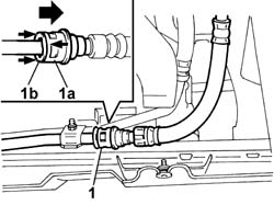
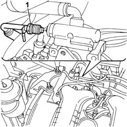
1. Disconnect the quick connector of the return pipe on the exchanger pipe, pusing part (1a) to the left while holding part (1b) in position; position a container below and drain the power steering fluid.
Lower the lift.
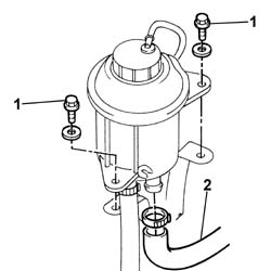
1. Unscrew the bolts securing the power steering fluid to the support bracket.
2. Raise the power steering fluid reservoir and remove the pipe carrying fluid to the pump by undoing the retaining band.
1. Undo the connector of the pipe supplying pressurized fluid to the power assisted steering box ont the pump.
Raise the lift.
Op. 1092G10 SINGLE ENGINE BELT - R.R..
Op. 1092A10 CRANKSHAFT PULLEY - R + R.
Op. 1092G14 ENGINE COMPONENT SINGLE BELT MOVING TENSIONER - R + R.
1. Undo the bolts fixing the power assisted steering pump pulley and remove.
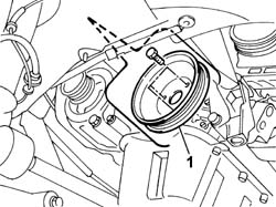
1. Undo the three bolts fixing the power assisted steering pump to the mounting.
Lower the lift.
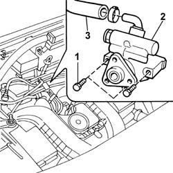
2. Remove the power assisted steering pump from the engine compartment.
3. Separate the fuel inlet pipe from the reservoir from the power assisted steering pump.
Refitting
Fit the fuel inlet pipe from the reservoir to the power assisted steering pump.
Place the power assisted steering pump in position and fasten it to the mounting using the fixing bolts.
| Fastening | Component | dia | Value (daNm) | |
|---|---|---|---|---|
| Bolt | POWER STEERING PUMP | M8 | 2.5 |
Fit the power steering pump drive pulley.
Op. 1092G14 ENGINE COMPONENT SINGLE BELT MOVING TENSIONER - R + R.
Op. 1092A10 CRANKSHAFT PULLEY - R + R.
Op. 1092G10 SINGLE ENGINE BELT - R.R..
Lower the lift.
Position the pipe carrying pressurised fluid to the power steering casing on the power steering pump and tighten the fitting.
| Fastening | Component | dia | Value (daNm) | |
|---|---|---|---|---|
| Connector | PIPE BTWN PUMP + POWER STEERING BOX | M16 X 1.5 | (On power steering pump) 4 |
Fit the pipe carrying fluid to the pump to the power steering reservoir and secure by means of the collar.
Secure the power steering fluid reservoir to the bracket.
| Fastening | Component | dia | Value (daNm) | |
|---|---|---|---|---|
| Bolt | POWER STEERING FLUID RESERVOIR | M6 | 0.85 |
Raise the lift.
Connect the quick connector of the fuel return pipe to the tank.
Op. 7055B54 PROTECTION/GUARD UNDER ENGINE - R.R..
Op. 4450B04 RIGHT FRONT WHEEL - R.R..
Connect the negative battery lead.
Remove the vehicle from the lift.
Refill the power assisted steering system using the appropriate fluid.
| Type | Component | Description | Qty. | |
|---|---|---|---|---|
| Oil [l] | POWER ASSISTED STEERING CIRCUIT | TUTELA GI/A |
The use of TUTELA HP 20 power assisted steering fluid is recommended for use in particularly harsh climatic conditions
| Type | Component | Description | Qty. | |
|---|---|---|---|---|
| Oil [l] | POWER ASSISTED STEERING CIRCUIT | TUTELA HP 20 |
The power assisted steering system is self-bleeding; this is done by steering completely to the right and the left with the engine running and the vehicle stationary.
After bleeding the air, check the power steering fluid level again and top up if necessary.
Removing
Position the vehicle on a lift.
1. Disconnect the quick connector of the return pipe, heat exchanger pipe side, and drain the power steering circuit fluid.
Drain the power assisted steering fluid into a suitable container.
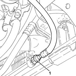
Proceed with the removal
Op. 4450B04 RIGHT FRONT WHEEL - R.R..
Proceed with the removal
Op. 1092G10 SINGLE ENGINE BELT - R.R..
Proceed with the removal
Op. 1092A10 CRANKSHAFT PULLEY - R + R.
Proceed with the removal
Op. 1092G14 ENGINE COMPONENT SINGLE BELT MOVING TENSIONER - R + R.
Proceed with the removal
Op. 1092G20 ENGINE COMPONENT SINGLE BELT FIXED TENSIONER - ONE - R + R.
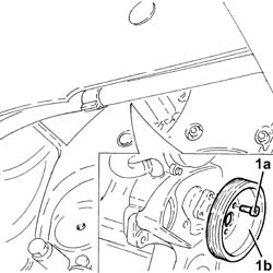
1. Undo the bolts (1a) and remove the power steering pump pulley (1b).
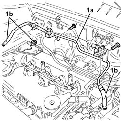
1. Remove the coolant return pipe to the engine cooling supply reservoir (1a) after disconnecting the pipes (1b) and unscrewing the fastenings.
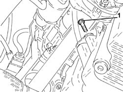
1. Undo the lower bolt securing the engine oil dipstick tube.
Proceed with the removal
Op. 1044B10 FUEL FILTER ASSEMBLY - R + R OR REPLACE.
Proceed with the removal
Op. 1080C24 E.G.R. SYSTEM SOLENOID - R + R.
Proceed with the removal
Op. 1060F50 FUEL RETURN MANIFOLD - R R.
1. Undo retaining bolt (1a) and remove the engine oil dipstick tube (1b).
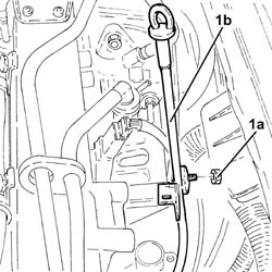
Release the electrical wiring from the fastenings on the pressure pump mount.
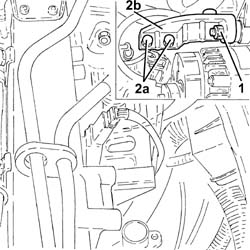
1. Loosen the upper bolt fixing the alternator to the mounting.
2. Undo the bolts (2a) and remove the upper alternator mount (2b).
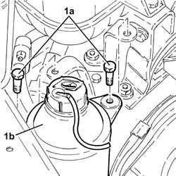
1. Undo the bolts (1a) fixing the power assisted steering fluid reservoir (1b).
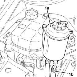
1. Raise the power steering fluid reservoir (1a) as necessary, loosen the collar and disconnect the supply pipe from the fluid reservoir to the power steering pump (1b), reservoir side.
Loosen the connector on the supply pipe from the pump to the power assisted steering box, power assisted steering pump side.
1. Undo the bolts (1a) then raise the power steering pump (1b) as necessary.
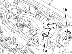
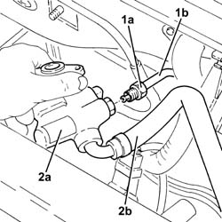
1. Undo the connector (1a) loosened previously and disconnect the supply pipe from the pump to the power assisted steering box (1b), power assisted steering pump side.
2. Remove the power assisted steering pump (2a) complete with supply pipe from fluid reservoir to power assisted steering pump (2b).
Refitting
Position the power assisted steering pump with supply pipe from fluid reservoir to power assisted steering pump near its seat.
Connect the supply pipe from the pump to the power assisted steering box, power assisted steering pump side and screw in the connector without tightening.
Position the power assisted steering pump in its housing and tighten the bolts to the recommended torque.
| Fastening | Component | dia | Value (daNm) | |
|---|---|---|---|---|
| Bolt | POWER STEERING PUMP | M8 | (Mount side) 2.3 - 2.8 |
Tighten the connector on the supply pipe from the pump to the power assisted steering box, power assisted steering pump side to the recommended torque.
| Fastening | Component | dia | Value (daNm) | |
|---|---|---|---|---|
| Connector | PIPE BTWN PUMP + POWER STEERING BOX | M16 | (Power assisted steering pump side) 3.6 - 4.4 |
Connect the supply pipe from the fluid reservoir to the power assisted steering pump, reservoir side, and tighten the band.
Place the power assisted steering fluid reservoir in its housing and secure it using the bolts.
Place the upper alternator support in its housing and secure it tightening the bolts to the cylinder block/crankcase to the recommended torque.
Tighten the upper alternator fixing bolt to the recommended torque.
| Fastening | Component | dia | Value (daNm) | |
|---|---|---|---|---|
| Bolt | ALTERNATOR ASSEMBLY | M10 | 4.5 ÷ 5.5 |
| Fastening | Component | dia | Value (daNm) | |
|---|---|---|---|---|
| Bolt | ALTERNATOR ASSEMBLY | M12 | 6.3 ÷ 7.7 |
Secure the electrical wiring to the fastenings on the pressure pump mount.
Place the engine oil dipstick tube back in its housing and tighten the upper bolt.
Proceed with the refitting
Op. 1060F50 FUEL RETURN MANIFOLD - R R.
Proceed with the refitting
Op. 1080C24 E.G.R. SYSTEM SOLENOID - R + R.
Proceed with the refitting
Op. 1044B10 FUEL FILTER ASSEMBLY - R + R OR REPLACE.
Tighten the lower bolt securing the engine oil dipstick tube.
Place the coolant return pipe to the engine coolant reservoir in position and secure it and connect the pipes.
Position the power assisted steering pump in its housing and secure it tightening the bolts to the recommended torque.
| Fastening | Component | dia | Value (daNm) | |
|---|---|---|---|---|
| Bolt | POWER STEERING PUMP DRIVE PULLEY | M8 | (Power assisted steering pump side) 2.3 - 2.8 |
Proceed with the refitting
Op. 1092G20 ENGINE COMPONENT SINGLE BELT FIXED TENSIONER - ONE - R + R.
Proceed with the refitting
Op. 1092G14 ENGINE COMPONENT SINGLE BELT MOVING TENSIONER - R + R.
Proceed with the refitting
Op. 1092A10 CRANKSHAFT PULLEY - R + R.
Proceed with the refitting
Op. 1092G10 SINGLE ENGINE BELT - R.R..
Proceed with the refitting
Op. 4450B04 RIGHT FRONT WHEEL - R.R..
Connect the rapid connector for the return pipe, heat exchanger side.
Refill the power steering circuit with the recommended fluid.
| Type | Component | Description | Qty. | |
|---|---|---|---|---|
| Oil [l] | POWER ASSISTED STEERING CIRCUIT | TUTELA GI/A | 1.3 |
The table shows the total quantity of oil present in the power steering circuit.
Bleed the power steering system as described below.
With the front wheels raised off the ground and the engine switched off, carry out 4 or -5 complete rotations of the steering wheel (left and right).
Check the reservoir fluid level and top up if necessary
Position the vehicle on the ground and start up the engine.
Carry out 4 or -5 complete rotations of the steering wheel (left and right).
Top up the power assisted steering fluid level in the reservoir.
Removing
Position the vehicle on a lift.
Disconnect the negative battery terminal.
| Description | Connector | |
|---|---|---|
| Battery | See A1H BATTERY ( ENGINE ) |
1. Disconnect the electrical connection from the air flow meter.
| Description | Connector | |
|---|---|---|
| 1 | Air flow meter | See K041 AIR FLOW METER |
2. Loosen the collar and disconnect the air intake sleeve to the turbocharger, air flow meter side.
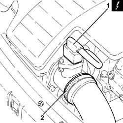
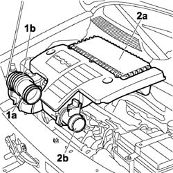
1. Loosen the band (1a) and disconnect the hose (1b) from the air intake.
2. Remove the air filter (2a) complete with air flow meter (2b) releasing it firstly from the pegs underneath and then from the rear fastening.
Carry out
Op. 7055B54 PROTECTION/GUARD UNDER ENGINE - R.R..
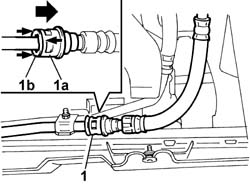
1. Disconnect the rapid connector for the power assisted steering system heat exchanger return pipe.
To disconnect the quick connector, press part (1a) to the left while holding part (1b) in position, then withdraw the pipe.
Carry out
Op. 4130B10 POWER STEERING FLUID RESEVOIR - R.R..
Carry out
Op. 1044B10 FUEL FILTER ASSEMBLY - R + R OR REPLACE.
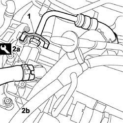
1. Unscrew the fitting of the delivery pipe from pump to power steering box.
2. Use the appropriate tool to loosen collar (2a) and disconnect supply pipe (2b) from the fluid reservoir to the power steering pump.
| Description | Code | |
|---|---|---|
| 2a | Caliper | 1.881.138.000 |
Carry out
Op. 1092C10 POWER STEERING AND/OR SELF-LEVELLING SUSPENSION PUMP DRIVE BELT - R + R.
Carry out
Op. 1092C14 POWER STEERING PUMP/SELF LEVELLING SUSPENSION PUMP PULLEY - R + R WITH BELT REMOVED.
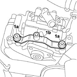
1. Undo the bolts (torx) (1a) and remove the bracket (1b).
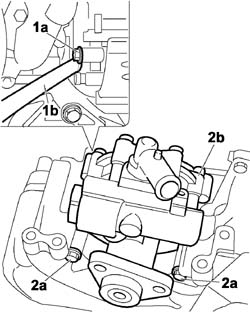
1. Working at the rear of the engine, undo the bolt (1a) fastened to support (1b).
2. Undo the three fixing bolts (2a) and remove the power steering pump (2b) from the mount.
Refitting
1. Position the power steering pump (1a) in its seat and tighten the three fixing bolts (1b) to the recommended torque.
| Fastening | Component | dia | Value (daNm) | |
|---|---|---|---|---|
| 1b |
2. Tighten the fixing bolt (2a) to the support (2b) and tighten to the recommended torque.
| Fastening | Component | dia | Value (daNm) | |
|---|---|---|---|---|
| 2a |
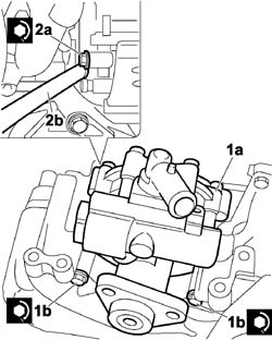
Position the bracket and tighten the fixing bolts.
1. Connect the delivery pipe from the pump to the power steering box and tighten the connector to the specified torque.
| Fastening | Component | dia | Value (daNm) | |
|---|---|---|---|---|
| 1 |
2. Connect the supply pipe (2a) from the fluid reservoir to the power assisted steering pump and tighten the band (2b) using the appropriate tool.
| Description | Code | |
|---|---|---|
| 2b | Caliper | 1.881.138.000 |
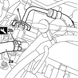
Carry out
Op. 1092C14 POWER STEERING PUMP/SELF LEVELLING SUSPENSION PUMP PULLEY - R + R WITH BELT REMOVED.
Carry out
Op. 1092C10 POWER STEERING AND/OR SELF-LEVELLING SUSPENSION PUMP DRIVE BELT - R + R.
Carry out
Op. 1044B10 FUEL FILTER ASSEMBLY - R + R OR REPLACE.
Carry out
Op. 4130B10 POWER STEERING FLUID RESEVOIR - R.R..
Connect the rapid connector for the power assisted steering system heat exchanger return pipe.
Carry out
Op. 7055B54 PROTECTION/GUARD UNDER ENGINE - R.R..
Position the air filter in its seat with the air flow meter, secure to the rear fastening and then to the underlying pins.
Connect the flexible sleeve to the air intake on the crossmember and tighten the retaining collar.
Connect the air intake sleeve to the turbocharger, air flow meter side, and tighten the collar.
Connect the electrical connection to the air flow meter.
| Description | Connector | |
|---|---|---|
| Air flow meter | See K041 AIR FLOW METER |
Connect the negative battery terminal.
| Description | Connector | |
|---|---|---|
| Battery | See A1H BATTERY ( ENGINE ) |
Remove the vehicle from the lift.
Removing
- Position the vehicle on the lift.
- Turn the ignition key to the OFF position.
- Disconnect the negative battery terminal.
| Description | Connector | |
|---|---|---|
| BATTERY | See A001 BATTERY |
Op. 4450B04 RIGHT FRONT WHEEL - R.R.
Op. 7055B54 PROTECTION/GUARD UNDER ENGINE - R.R.
Op. 1092C10 POWER STEERING AND/OR SELF-LEVELLING SUSPENSION PUMP DRIVE BELT - R + R
Position a suitable container for collecting the power steering fluid.
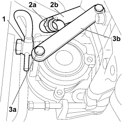
1. Disconnect the fitting on the high pressure pipe carrying fluid from the power steering pump to the box. Place a container beneath the vehicle and drain the fluid present.
2. Use the appropriate tool to remove collar (2a) retaining fluid inlet pipe (2b) from the reservoir.
3. Undo the fixing bolts (3a) and remove the bracket (3b).
1. Undo retaining bolts (1a) and remove pulley (1b).
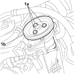
1. Undo the bolts (1a) and remove the power steering pump (1b) fromthe vehicle.
Refitting
1. Position the power steering pump (1a) in its seat and tighten the three fixing bolts (1b) to the recommended torque.
| Fastening | Component | dia | Value (daNm) | |
|---|---|---|---|---|
| 1b | Bolt | POWER STEERING PUMP | M8 X 1.25 | 2.2 |
1. Position the pulley (1a) in its seat and tighten the three fixing bolts (1b) to the recommended torque.
| Fastening | Component | dia | Value (daNm) | |
|---|---|---|---|---|
| 1b | Bolt | POWER STEERING PUMP DRIVE PULLEY | M8 | 2.5 |
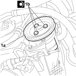
1. Position the bracket (1a) in its seat and tighten the fixing bolts (1b) to the recommended torque.
| Fastening | Component | dia | Value (daNm) | |
|---|---|---|---|---|
| 1b | Bolt | POWER STEERING PUMP | M8 X 1.25 | 2.2 |
Op. 1092C10 POWER STEERING AND/OR SELF-LEVELLING SUSPENSION PUMP DRIVE BELT - R + R
Op. 7055B54 PROTECTION/GUARD UNDER ENGINE - R.R.
Op. 4450B04 RIGHT FRONT WHEEL - R.R.
Op. 0010T71 POWER STEERING FLUID CHECK LEVEL AND TOP UP IF NECESSARY
- Connect the negative battery terminal.
| Description | Connector | |
|---|---|---|
| BATTERY | See A001 BATTERY |
- Remove the vehicle from the lift.
Parts & tools for this job For 2000 Fiat Doblò
- TOOLTie rod end toolSearch: tie rod end puller
- TOOLBall joint separatorSearch: ball joint separator
- FLUIDPower steering fluidSearch: Fiat power steering fluid
Links open Amazon search results in a new tab. As an Amazon Associate I earn from qualifying purchases.