
Stop lights
- Make
- Fiat
- Model
- Punto (176) Factory Service Manual
- Year
- 1993–1999
- Section
- Seat belt pretensioner › Stop lights
Stop lights
The various bulbs are checked by a system of “feeling” the voltage drop which occurs on resistive dividers consisting of the resistors of the bulbs which must be monitored and by low-value (0.1Ω) reference resistors, which in this case are inside the check panel control unit (14 A).
The principle on which the check panel’s check is based, for the bulbs of the services in question, is to continuously compare the voltage applied upstream of the reference resistors (battery voltage) with the voltage drop which occurs on the divider consisting of the reference resistors and the bulbs. This voltage difference must never be less than a particular value, usually a few millivolts, on which the check panel’s electronics are based for the check panel to perform its function.
In other words, if the bulbs are working, there is a constant voltage drop on the reference resistors, which is always greater than a threshold value determined by the check panel’s electronics. Under these conditions, the check panel does not indicate any faults.
If a bulb blows, or if the circuit is broken, there is no longer a voltage drop on the relevant reference resistor and the voltage “measured” by the check panel downstream of the resistor exceeds the established threshold.
Under these conditions, the check panel immediately recognizes the fault and indicates it to the user by means of the relevant warning lamp on the display.
So when the brake pedal is pressed, if one of the two bulbs is faulty, the check panel indicates the fault. If the supply fuse (F1) is broken, the check panel does not indicate it.
Wiring diagram showing connection of stop lights
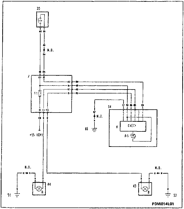
- 7 Junction unit:
- F1 Circuit protection fuse
- 14 Instrument panel
- A Check panel module
- A1 Stop lights fault warning lamp
- 16 Left dashboard earth
- 20 Stop lights switch
- 43B Rear right lights cluster
- 44A Rear left lights cluster
- 51 Rear left earth
- 52 Rear right earth
- N.D. Connector blocks
Parts & tools for this job For 1993 Fiat Punto
- TOOLOBD2 scanner with SRSSearch: OBD2 scanner ABS SRS
- TOOLTrim removal tool kitSearch: trim removal tool kit
Links open Amazon search results in a new tab. As an Amazon Associate I earn from qualifying purchases.