| Assembly Special Tool(s) | | Installer, Wheel Hub Bearing Cup 204-017 (14-010) | | | Installer, Front Wheel Hub Bearing Cup/Seal 204-050 (14-024) | | | Preload Gauge 205-067 (15-041) | | | Installer, Rear Wheel Hub Seal 205-075 (15-036) | | | Installer, Drive Pinion Seal 205-115 (15-058) | | | Socket, Drive Pinion Nut 205-175 (15-073) | | | Compressor, Valve Spring 303-060 (21-024) | | | Adaptor for 303-060 303-060-02 (21-024-02) | | | Mounting Plate for 303-435-06 303-435-14A (21-212A) | | | Adaptor for 303-060 306-060-07 (21-024-07) | | | Installer, Input Shaft Seal 307-210 (17-041) | | | Holding Fixture, Dial Indicator Gauge ( Output Shaft End Play) 308-194B (16-059B) | General Equipment Dial indicator gauge with bracket Hot air gun Materials Name Specification Manual transmission fluid WSD-M2C200-C Sealer, transaxle housing WSK-M2G348-A5 Temperature reduction spray Assembly | | -
CAUTION:Bearing races require a heating and cooling procedure and special tools for installation. This procedure must be followed to provide accurate preload measurements. Clean and check all parts carefully before assembly. | | | -
NOTE:Clean and check all parts thoroughly and install new if necessary. | | | -
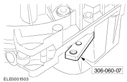
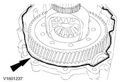
Install the reverse gear idler shaft. - Apply sealer to the mating surface of the reverse gear idler shaft.
- Install the reverse gear idler shaft, using a locating bolt.
- Remove the location bolt and install the original bolts.
| | | -
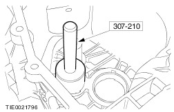
CAUTION:The press force must not exceed 15 kN. NOTE:Using a suitable press, install the bearing cup. Using the special tool, install the input shaft bearing cup. - Using a hot air gun, heat the transaxle housing to approximately 80°C.
| | | -
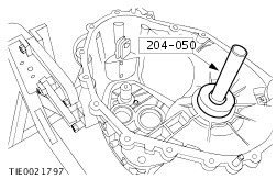
CAUTION:The press force must not exceed 15 kN. NOTE:Using a suitable press, install the bearing cup. Using the special tool, install the output shaft bearing cup. - Using a hot air gun, heat the transaxle housing to approximately 80°C.
| | | -
CAUTION:The press force must not exceed 15 kN. NOTE:Using a suitable press, install the bearing cup. Using the special tool, install the differential bearing cup. - Using a hot air gun, heat the transaxle housing to approximately 80°C.
| | | -
CAUTION:The press force must not exceed 15 kN. NOTE:Using a a suitable press, install the bearing cup. Using the special tool, install the input shaft bearing cup. - Install a 1.00 mm measuring shim.
- Using a hot air gun, heat the transaxle housing to approximately 80°C.
| | | -
CAUTION:The press force must not exceed 15 kN. NOTE:Using a suitable press, install the bearing cup. Using the special tool, install the output shaft bearing cup into the clutch housing. - Install a 1.00 mm measuring shim.
- Using a hot air gun, heat the transaxle housing to approximately 80°C.
| | | -
CAUTION:The press force must not exceed 15 kN. NOTE:Using a suitable press, install the bearing cup. Using the special tool, install the differential bearing cup into the clutch housing. - Install a 1.10 mm measuring shim.
- Using a hot air gun, heat the transaxle housing to approximately 80°C.
| | | -
NOTE:Do not lubricate the roller bearings. Engage fourth gear. | | | -
NOTE:Do not lubricate the roller bearings. Install the input shaft and output shaft. | | | -
NOTE:Do not lubricate the roller bearings. Install the differential. | | | -
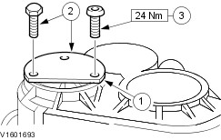
NOTE:Make sure that the transaxle housing mating surfaces are clean. Assemble the transaxle housing to the clutch housing. - Install the special tool.
| | | -
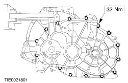
Tighten the transaxle housing retaining bolts. | | | -
Install the special tool. - Position the measuring bar on the fourth gear wheel.
| | | -
Using the special tool, align the input shaft for measuring. - Turn the input shaft approximately 20 times to settle the bearings.
| | | -
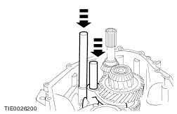
NOTE:Carry out the preparations and the measurement three times and calculate the average value of the measurements. Measure the input shaft end float. - Using a suitable lever, lift the input shaft.
- Note the resulting measurement (for example: 0.22 mm).
- Example: 0.22 mm + 0.23 mm + 0.21 mm divided by three = 0.22 mm.
| | | -
Align the output shaft for measuring. - Turn the output shaft 20 times to settle the bearings (via input shaft, refer to previous steps).
| | | -
NOTE:Carry out this step and the following step three times and calculate the average measurement. Measure the output shaft end float. - Lift the output shaft with a suitable lever and note the resulting measurement, (for example: 0.32 mm).
- Example: 0.32 mm + 0.34 mm + 0.33 mm divided by three = 0.33 mm.
| | | -
Using the special tool, align the differential for measuring. - Turn the output shaft 20 times and at the same time press down the differential.
| | | -
NOTE:Carry out this step and the following step three times and calculate the average measurement. Measure the differential end float. - Using the special tools, lift the differential and note the resulting measurement (for example: 0.34 mm).
- Example: 0.34 mm + 0.36 mm + 0.38 mm divided by three = 0.36 mm.
| | | -
Calculate the required input shaft shim thickness. - Required shim thickness 1.00 mm.
- Measured input shaft end float 0.22 mm.
- Preload figure for end float -0.05 mm.
- Required shim: 0.22 mm - 0.05 mm + 1.00 mm = 1.17 mm.
| | | -
Calculate the required output shaft shim thickness. - Calculated output shaft end float 0.33 mm.
- Preload figure for end float 0.13 mm.
- Required shim: 1.00 mm + 0.33 mm + 0.13 mm = 1.46 mm.
| | | -
Calculate the required differential shim thickness. - Required shim thickness 1.10 mm.
- Calculated differential end float 0.36 mm.
- Required shim: 1.10 mm + 0.36 mm + 0.33 mm = 1.79 mm.
| | | -
Remove the input shaft, the output shaft and the differential. | | | -
Remove the bearing cups, refer to previous steps. - Remove the input shaft bearing cup.
- Remove the output shaft bearing cup.
- Remove the differential bearing cup.
| | | -
Install the shims and bearing cups, refer to previous steps. - Install the required shims, refer to previous steps.
- Install the bearing cups.
| | | -
Fabricate an installation hook for the reverse gear idler. - Diameter of the wire: 3 mm.
| | | -
Assemble the reverse gear idler - Install the lower thrust washer.
- Install the needle roller bearing.
- Install the reverse gear idler (small collar facing downwards).
- Install the upper thrust washer.
- Install the reverse gear idler shaft mounting bracket.
| | | -
NOTE:Install the reverse gear idler with the small collar facing downwards. Using the installation hook, install the reverse gear idler and mounting bracket. | | | -
NOTE:Lubricate the roller bearings with manual transmission fluid. Install the input shaft and output shaft. - Install the input shaft and output shaft together and move them aside.
- Remove the installation hook.
| | | -
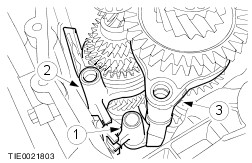
NOTE:Make sure that the input shaft is in the neutral position. Install the selector forks. - Install the first and second gear selector fork.
- Install the third and fourth gear selector fork.
- Install the fifth and reverse gear selector fork.
| | | -
NOTE:If the holes for the reverse gear idler shaft bracket retaining bolts do not line up exactly, check the installation position of the reverse gear idler shaft thrust washers. Install the reverse gear idler shaft retaining bolts. | | | -
NOTE:Make sure that the selector rods are the same height. Install the selector rods. | | | -
Install the differential assembly. - Install the magnetic disc.
| | | -
Apply approximately a 2 mm bead of sealer to the inside edge of the transaxle mating surface. | | | -
CAUTION:Using adhesive tape, cover the input shaft splines, to prevent damage to the input shaft oil seal. NOTE:The transaxle housing must not be turned before tighten the retaining bolts. Install the transaxle housing retaining bolts. | | | -
NOTE:Make sure that the selector mechanism is in the neutral position. Install the selector mechanism. | | | -
CAUTION:If the turning torque is too high, all the measurements (to establish the required shim thickness) must be repeated. Using the special tools, measure the turning torque. | | | -
Install the vehicle speed sensor (VSS). | | | -
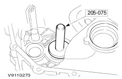
Using the special tool, install the halfshaft oil seals on both sides (right-hand side shown). | | | -
Install the clutch slave cylinder and release bearing assembly. - Apply sealer to the mating faces of the clutch housing.
| | |