| Assembly Special Tool(s) | | Dial gauge stand 205 - 070 (15 - 022 A) | | | Remover, pinion gear oil seal 205 - 078 (15 - 048) | | | Installer, drive halfshaft oil seal 308 - 039 (16 - 018) | | | Installer, input shaft oil seal 308 - 041 (16 - 020) | | | Extractor, oil pump 307 - 203 (17 - 034) | | | Primary unit locking tool 307 - 204 (17 - 035) | | | Remover, housing half (primary unit) 307 - 206 (17 - 037) | | | Remover, secondary unit 307 - 207 (17 - 038) | | | Remover, sensor shaft 307 - 208 (17 - 039) | | | Spring washer compressor 307 - 209 (17 - 040) | | | Installer, input shaft oil seal 307 - 210 (17 - 041) | | | Guide sleeve, forward clutch piston 307 - 213 (17 - 044) | | | Guide sleeve, reverse clutch piston 307 - 214 (17 - 045) | | | Gauge bar for measuring adjusting shim 307 - 300 (17 - 055) | | | Compressor, valve spring 303 - 060 (21 - 024) | | | Adaptor for 303-060 303 - 060 - 02 (21 - 024 - 02) | General Equipment Dial gauge Socket wrench, 41 mm Socket wrench, 46 mm Internal extractor Feeler gauges Depth gauge Materials Name Specification Automatic transmission fluid WSS-M2C202-B Cable ties Sealer SQM-4G9523-A Vaseline SM-1C115-A Assembly | | -
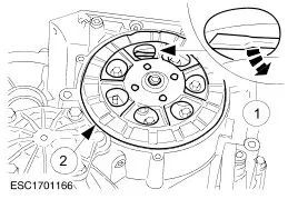
CAUTION:Only use automatic transmission fluid. NOTE:Clean all parts carefully and check them for wear and damage. NOTE:The gaskets, oil seals, O-rings, circlips and self-locking nuts must not be reused. NOTE:Coat all moving parts and sealing rings with automatic transmission fluid before assembly. NOTE:Immerse the friction plates in automatic transmission fluid for at least 15 minutes before installing them. NOTE:When carrying out repairs, only use new pattern clutch plates. NOTE:Immerse the new design clutch plates in automatic transmission fluid for at least one hour before installing them. Clutch plate identification. - New pattern.
- Old pattern.
| | | -
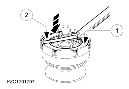
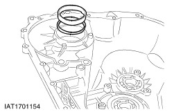
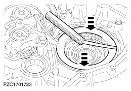
Install the forward clutch actuating piston. - Fit the guide sleeve.
- Fit the two oil seals to the actuating piston.
- Press the actuating piston in, turning it slightly until it meets the stop.
- Fit the pressure plate.
| | | -
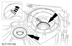
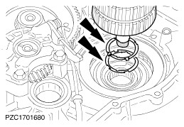
Locate the spring washer so that the spring pin (if equipped) engages into one of the cut-outs in the spring washer. Fit the spring washer. - Depress the spring washer using the special tool.
- Fit the circlip.
| | | -
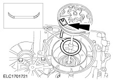
NOTE:The step in the thrust washer (thicker washer) must face upwards. Install the forward clutch. - Fit the clutch plate pack complete.
- Fit the circlip.
| | | -
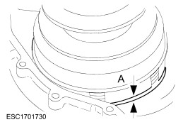
NOTE:The ring groove for the circlip is offset towards the top (measurement 'A'). Clutch assembly - Thrust washer with step and spacer ring (measurement 'A' about 2 mm).
- Spacer ring
| | | -
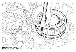
NOTE:Required value: 0,7 - 2,1 mm. If the value is outside this range, check that the clutch pack is complete. Determine the forward clutch end float. - Press the clutch pack together.
- Measure the end float between the circlip and the clutch plate assembly using feeler gauges .
| | | -
NOTE:Determine the circlip gap. Insert the thickest possible circlip (circlips supplied in thicknesses of 1,65 mm; 1,85 mm and 2,10 mm for service). Fit the secondary unit bearing inner race. - Heat the bearing cone to approx. 80 °C and install it.
- Fit the circlip.
| | | -
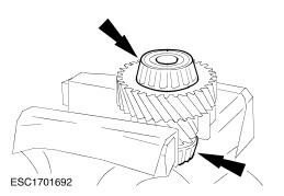
Assemble the reduction gear. - Heat the taper roller bearing to approx. 80 °C and install it.
- Make sure that the bearing is seated correctly using a suitable length of tubing. Do not strike directly on the bearing.
| | | -
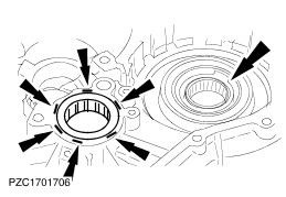
Install the input shaft needle roller bearing and fit the secondary unit roller bearings. - Heat the bearing areas to approx. 80°C.
- Secure the roller bearing by staking it.
| | | -
Install the reduction gear bearing cone. - Fit the bearing cone with a measuring shim (2,10 mm or at least 0,3 mm thinner than the previously fitted shim).
| | | -
Install the reduction gear bearing cap. - Fit the bearing cone in the bearing cap.
| | | -
Prepare the reduction gear for measuring. - Turn the reduction gear several times to settle the bearings.
- Make sure the bearing cone is seated correctly.
| | | -
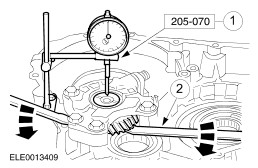
Measure the end float. - Fit the dial gauge and zero it.
- Lift the reduction gear evenly using two levers and take a reading.
- Repeat the measurement procedure according to the previous and this job step. Calculate the average value.
| | | -
NOTE:The value should be rounded up or down by a maximum of 0,02 mm depending on the adjusting shims available. NOTE:Adjusting shims are available in thicknesses of 2,06 - 3,06 mm in steps of 0,04 mm. Measure the adjusting shim to be fitted. - Measured end float: + 0,32 mm
- Bearing preload: + 0,05 mm
- Calculated shim thickness: 2,47 mm
- Thickness of shim to be fitted: 2,46 mm
| | | -
Remove the reduction gear again. | | | -
Fit the planetary gear carrier with the previously fitted thrust washer and adjusting shim. - Shim
- Thrust washer.
- Planetary gear carrier
| | | -
NOTE:Do not oil the taper roller bearing. Fit the differential and the primary unit. - Primary unit.
- Differential
| | | -
Fit the differential measuring shim. - Fit the measuring shim (3,80 mm thick) and the bearing cone.
| | | -
Fit the primary and secondary unit ball bearings. - Turn the pitot tube anti-clockwise as far as it will go.
| | | -
- Screw in an M6x30 mm bolt.
| | | -
NOTE:Thoroughly clean the sealing surfaces on the two halves of the transmission casing. Assemble the transmission housing. - Settle the transmission housing using the installation drift until the housing bolts can be located.
- Screw on the nuts of the primary unit fingertight.
| | | -
Tighten the transmission housing uniformly. - Insert the assembly plug.
- Remove the pitot tube fixing (cable tie) and remove the associated bolt.
| | | -
Tighten the primary unit nut. - Insert the special tool to immobilise the forward clutch.
- Tighten the nut using a 46 mm socket .
| | | -
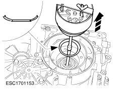
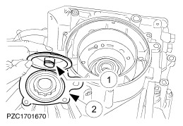
CAUTION:Turn pitot pipe clockwise until it reaches the stop. NOTE:Position of the spring washer. Install the oil pump with the spring washer. - Insert the pitot filling tube into the oil pump.
| | | -
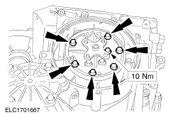
Tighten the oil pump bolts evenly, working diagonally. | | | -
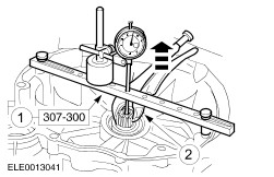
NOTE:Adjusting shims are available in the following thicknesses (input shaft end float setting): 0,75 mm - 2,08 mm in steps of 0,08 mm. Measure the input shaft end float. - Fit the gauge bar together with the dial gauge and zero the gauge.
- Lift the input shaft carefully with a pair of pliers and read off the value on the dial indicator gauge. Required value: 0,05 - 0,20 mm.
| | | -
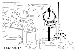
Fit the dial indicator gauge on the differential. - Turn the differential several times to settle the bearings.
- Attach the dial gauge and zero it with a preload of 1,0 mm.
| | | -
Measure the differential end float. - Lift the differential and measure the end float.
| | | -
NOTE:Combine a number of shims until the required shim thickness is obtained. Round up the value in each case. Adjusting shims are available in the following thicknesses (in mm) 0,06; 0,10; 0,20; 4,2; 4,6; 5,0 Measure the adjusting shim to be fitted. - Measured end float: + 0,33 mm
- Bearing preload: + 0,30 mm
- Calculated shim thickness: 4,83 mm
- Thickness of shim to be fitted: 4,86 mm
| | | -
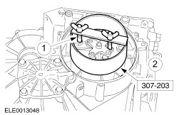
Remove the oil pump. - Screw in the threaded pins.
- Withdraw the oil pump evenly from the housing using the special tool.
| | | -
Remove the oil pump. - Withdraw the oil pump complete with the special tool.
- Remove the spring washer.
| | | -
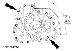
Unscrew the housing bolts. - Unscrew all the bolts apart from two opposite each other.
- Turn the transmission through 90 degrees and remove the remaining bolts.
| | | -
NOTE:Turn the pitot tube counter-clockwise up to the stop. Fit the special tool. | | | -
Separate the transmission housing evenly. | | | -
NOTE:Adjusting shims are available in various thicknesses. The thick adjusting shim must always be inserted towards the housing. Fit the measured adjusting shim. - Remove the measuring shim and replace it with the measured adjusting shim.
| | | -
Remove the differential and the primary unit. - Differential
- Primary unit.
| | | -
Remove the planetary gear carrier. - Planetary gear carrier.
- Shim
- Thrust washer.
| | | -
Insert the oil spray tube and tighten the bolt. | | | -
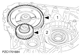
Install the reduction gear and the differential. - Differential
- Reduction gear.
| | | -
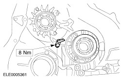
Install the reduction gear bearing cap. - Fit the bearing cone in the bearing cap. Fit the bearing cap.
- Tighten the bolts.
- Swing the parking pawl forwards and hook the parking pawl spring in place.
| | | -
Install the reverse clutch actuating piston. - Install the guide sleeve.
- Press the actuating piston in, turning it slightly, until it meets the stop.
| | | -
Secure the actuating piston. - Fit the spring washer.
- Fit the circlip.
| | | -
NOTE:When carrying out repairs, use new pattern clutch plates. Immerse the clutch plates in automatic transmission fluid for at least one hour before installing them. Clutch plate identification. - New pattern.
- Old pattern.
| | | -
NOTE:The clutch assembly depends on the model year. NOTE:The step in the thrust washer (thicker washer) must face upwards. Install the reverse clutch. - Insert the clutch pack (with stepped thrust washer and spacer ring).
- Fit the circlip.
| | | -
NOTE:The ring groove for the circlip is offset towards the top (measurement 'A'). Clutch assembly - Thrust washer with step and spacer ring (measurement 'A' about 2 mm)
- Spacer ring
| | | -
NOTE:Required value: 0,7 - 2,1 mm. If the value is any different, check the clutch pack for completeness. Measure the reverse clutch end float. - Press the clutch pack together.
- Measure the end float between the circlip and the clutch pack using a feeler gauge.
| | | -
Install the planetary gear carrier. - Put the thrust washer and measured adjusting shim (from previous job step) into position.
| | | -
NOTE:Required value: 31,0 - 33,5 mm. If the required value is exceeded, the planet carrier is not installed correctly. | | | -
Install the primary unit and forward clutch. | | | -
NOTE:If this value is exceeded, the clutch plate pack is not fully home. Check the primary unit installation depth. - Primary unit installation depth: 2 mm
| | | -
NOTE:Steel belt direction indicator arrow Install the steel belt and secondary unit. - Position the secondary unit and steel belt so that the steel belt can be fitted onto the primary unit.
- Bring the secondary unit and steel belt into their final position.
| | | -
Install the steel belt and secondary unit. - De-tension the secondary unit.
- Remove the special tool.
- Remove the nut and the spacer ring.
| | | -
Install the transmission pitot chamber. - Remove the cable ties.
- Secure the transmission pitot chamber.
| | | -
- Turn the pitot tube anti-clockwise as far as it will go.
| | | -
CAUTION:Apply the sealant thinly using a foam roller. Sealant must not be allowed to enter the transmission. NOTE:Thoroughly clean the sealing surfaces on the casing. Apply sealer. - The sealing surface must be dry.
- Apply sealant ,spreading it evenly over the sealing surface.
| | | -
Assemble the transmission housing. - Tap the transmission housing down using the installer until the primary unit nut can be fitted.
- Align the housing by turning the primary unit nut.
| | | -
CAUTION:The transmission housing must not be turned (viewed from below). Tighten the housing bolts uniformly. - Tighten the housing bolts.
- Insert the assembly plug.
- Remove the pitot tube fixing (cable tie) and remove the associated bolt.
| | | -
Fit the selector shaft oil seal. | | | -
Install the selector shaft. - Slide the selector shaft in from the oil seal side and screw in the stop bolt.
- Attach the selector lever.
- Hook the selector linkage in place and tighten the engagement plate.
| | | -
Tighten the secondary unit nut. - Turn the selector lever until the parking pawl engages.
- Tighten the nut using a 41 mm socket .
| | | -
CAUTION:Turn pitot pipe clockwise until it reaches the stop. Fit the secondary unit inside cover. - Fit the oil seal.
- Fit the gasket.
| | | -
Fit the secondary unit housing cover. | | | -
NOTE:Correct position of the spring washer. Install the oil pump with the spring washer. - Insert the oil filler tube.
- Fit the oil seals and insert them with Vaseline .
| | | -
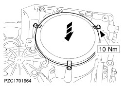
CAUTION:Before tightening the oil pump, make sure that the upper oil seal remains only partially visible in order to ensure that it seats correctly. Tighten the oil pump bolts evenly, working diagonally. | | | -
Install the engine pitot chamber. - Fit the engine pitot tube and turn it anti-clockwise as far as it will go.
- Lay the engine pitot chamber in place.
- Swivel back the engine pitot tube.
| | | -
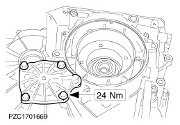
NOTE:Align the bolt holes (centre the engine pitot chamber). Install the engine pitot chamber. - Screw in the engine pitot tube bolt five turns.
- Secure the engine pitot chamber.
- Tighten the engine pitot tube bolt to 10Nm.
| | | -
Fit the primary unit blanking cover. - Fit the O-ring in the housing.
| | | -
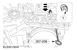
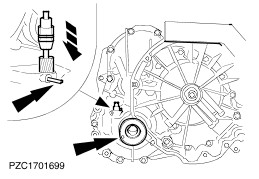
Install the transmission gear sensor. - Fit the sensor and swivel it to the right.
- Slide in the sensor shaft (including spring) using the special tool.
| | | -
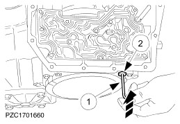
Install the transmission gear sensor. - Insert the retaining clip.
- Remove the special tool.
| | | -
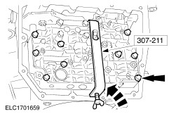
Install the adjusting sleeve. - Using a 4 mm Allen key, push the adjusting sleeve in against the spring and hold it in position.
- Tighten the blanking plug.
| | | -
Set the adjusting sleeve (basic adjustment). - Screw in the adjusting sleeve clockwise until resistance is felt then unscrew it six turns.
- Fit the dust cap.
| | | -
Install the valve body - Secure the engaging finger of the engagement plate in the manual gearshift valve.
- Insert the secondary lever behind the collar of the sensor sleeve.
| | | -
NOTE:Bolts (Finis Code: 1 649 091) must be renewed. Install the valve body - Screw in the bolts until they start to take up.
- Screw in the remaining bolts (five) until they start to take up.
| | | -
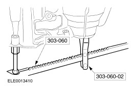
NOTE:Keep to the tightening sequence and torque specifications without fail, otherwise the valve body may misfunction. Tighten the valve body bolts in two stages. | | | -
NOTE:The valve cap must be seen to move at the same time. Check that the pistons move freely. - Press in the piston by hand as far as possible (approx. 2 - 3 mm).
- The piston must return to the initial position by itself.
| | | -
Install the oil strainer and start inhibit switch. - Fit the oil seal and the oil strainer.
- Secure the oil strainer.
- Screw in the start inhibit switch with a new oil seal.
| | | -
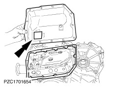
CAUTION:Clean the permanent magnet before installation. NOTE:Position of the permanent magnet. Fit the sump. - Fit the gasket to the transmission.
| | | -
Secure the sump uniformly. | | | -
Fit the front drive halfshaft oil seals. | | | -
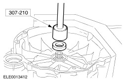
Install the input shaft oil seal. | | | -
NOTE:Install the input shaft carefully, it could fall into the transmission housing. Install the speedometer drive gear. - Insert the sleeve with the drive gear.
- Insert the two assembly plugs.
| | | -
Detach the transmission from the assembly stand. | | |