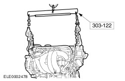
| Installation Special Tool(s) | | Lifting Bracket, Engine 303-122 (21-068A) | | | Remover/Installer, Hose Clamp 303-397 (24-003) | General Equipment Auxiliary plug Assembly stand Tensioning strap Jib crane Installation All vehicles | | -
General Notes - If necessary, use Special Tool 303-397 to install coolant and ventilation hoses.
- The engine mounting positions are given looking from the transmission towards the engine.
| | | -
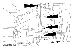
CAUTION:Ensure that the two guide sleeves are installed. Attach the engine to the transmission. | | | -
Screw in the left-hand flange bolts. | | | -
Screw in the right-hand flange bolts. - Attach the gearshift cable bracket.
| | | -
Place the engine and transmission assembly on the assembly stand. - Support the transmission with wooden blocks and secure with a tensioning strap.
| | | -
Raise the vehicle.
For additional information, refer to: Lifting (100-02 Jacking and Lifting, Description and Operation).
| | | -
Locate the engine and transmission assembly with assembly stand in the installation position under the vehicle. | | | -
Lower the vehicle and guide the engine and transmission assembly into the engine compartment. | | | -
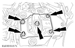
NOTE:Do not fully tighten the rear engine mount bolts and nuts at this stage. Attach the rear engine mount. | | | -
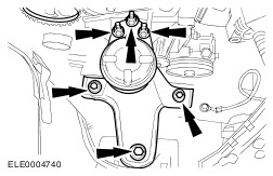
NOTE:Do not fully tighten the front engine mount bolts and nuts at this stage. Attach the front engine mount. | | | -
Remove the tensioning strap. | | | -
Raise the vehicle.
For additional information, refer to: Lifting (100-02 Jacking and Lifting, Description and Operation).
- Pull the assembly stand out from under the engine and transmission assembly.
| | | -
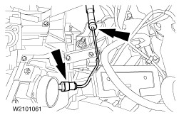
Attach the clutch master cylinder pipe. | | | -
CAUTION:The inner joint must not be bent more than 18 degrees, the outer one no more than 45 degrees. Install the left-hand front drive halfshaft in the transmission. - Remove the auxiliary plug from the transmission opening.
| | | -
NOTE:Install a new intermediate shaft centre bearing cap and nuts. NOTE:Insert the intermediate shaft into the transmission until the intermediate shaft bearing contacts the rib of the intermediate shaft bracket. Install the front drive halfshaft with intermediate shaft. - Remove the auxiliary plug from the transmission opening.
| | | -
Install the engine support insulator. | | | -
Attach the vehicle speed sensor (VSS) connector. | | | -
Attach the reversing lamp switch connector. | Vehicles with air conditioning | | -
Attach the power steering pump bracket with drive belt tensioner. | All vehicles | | -
Attach the lower suspension arm ball joint on both sides. | | | -
Attach the gearshift and selector cables to the abutment and lock by turning the catch counter-clockwise. - Clip the gearshift cable to the gearshift lever.
- Clip the selector cable to the selector lever.
| | | -
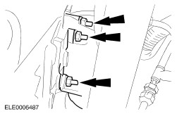
Attach the connector for the heated oxygen sensor (HO2S). | | | -
Attach the connector for the crankshaft position sensor (CKP sensor). | | | -
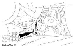
Attach the connector for the oil pressure switch. | | | -
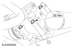
Attach the exhaust manifold to the front exhaust pipe. - Attach the exhaust manifold to the cylinder head.
| | | -
Detach the flexible pipe support. | | | -
Attach the starter motor ground cable. | Vehicles without air conditioning | | -
Attach the power steering pump with carrier plate. | | | -
Attach the bracket of the power steering hydraulic line. | Vehicles with air conditioning | | -
Install the A/C compressor. | | | -
Attach the bracket for the power steering high-pressure pipe. | All vehicles | | -
Install the auxiliary drive belt. For additional information, refer to: (303-05 Accessory Drive) Accessory Drive Belt (Removal and Installation), Accessory Drive Belt - Vehicles Built Up To: 03/2002, Vehicles Without: Accessory Drive Belt Tensioner (Removal and Installation), Accessory Drive Belt - Vehicles Built From: 03/2002, Vehicles Without: Accessory Drive Belt Tensioner (Removal and Installation). | | | -
Attach the carbon canister vacuum line. | | | -
Attach the coolant and heating hoses. - Reservoir coolant hose.
- Heater hose.
- Coolant hose.
| Vehicles without air conditioning | | -
Attach the connector and cable. - Connect the generator.
- Attach the power steering pump connector.
| Vehicles with air conditioning All vehicles | | -
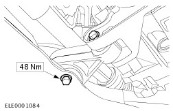
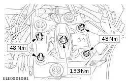
Tighten the rear engine mount. | | | -
Tighten the front engine mount. | | | -
Attach the vacuum hoses. - Fuel pressure regulator vacuum hose.
- Brake servo vacuum hose.
| | | -
Attach the engine wiring harness connector - Clip in the gearshift cables.
| | | -
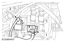
Attach connectors. - Ignition coil (EI).
- Condenser.
| | | -
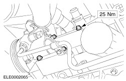
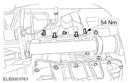
NOTE:Use a new exhaust manifold gasket. Attach the exhaust manifold (shown from below). | | | -
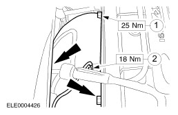
Attach the exhaust manifold heat shield and engine ground cable. - Exhaust manifold heat shield.
- Engine ground cable.
| | | -
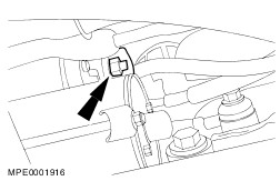
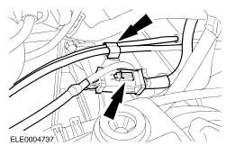
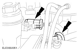
Attach the engine wiring harness multiplug and the connector for the camshaft position (CMP) sensor. | | | -
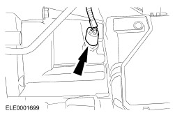
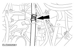
Attach the accelerator cable. - Attach the clip.
- Screw the cable into the bracket.
| | | -
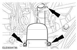
Install the air cleaner with the intake hose. - Intake hose.
- Attach the mass air flow (MAF) sensor multiplug.
- Attach the crankcase ventilation hose to the cylinder head.
| | | -
Clip on the power steering reservoir. | | | -
Tighten the right and left-hand suspension strut nuts. | | | -
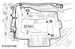
Install the battery tray. - Clip the wiring harness in place.
- Tighten the bolts.
- Clip on and attach the connector.
| | | -
Install a new oil filter. | | | -
Fill up with engine oil.
For additional information, refer to: Specifications (303-01A Engine - 1.4L/1.6L, Specifications).
| | | -
Fill up with coolant.
For additional information, refer to: Cooling System Draining, Filling and Bleeding (303-03 Engine Cooling, General Procedures).
| | | -
Bleed the clutch hydraulic system.
For additional information, refer to: Clutch System Bleeding - Vehicles With: 5-Speed Manual Transmission (iB5) (308-00 Manual Transmission/Transaxle and Clutch - General Information, General Procedures).
| | | -
Install the battery.
For additional information, refer to: Battery (414-01 Battery, Mounting and Cables, Removal and Installation).
| Vehicles with front and rear power windows | | -
Initialize the window winder motors.
For additional information, refer to: Door Window Motor Initialization (501-11 Glass, Frames and Mechanisms, General Procedures).
| |