
Cylinder head - overhaul (page 4 of 4)
- Make
- Land Rover
- Model
- Discovery II
- Section
- OVERHAUL
ENGINE - V8
12-2-66 OVERHAUL
26. Remove worn valve seat.
CAUTION: Take care not to damage the
counterbore in the cylinder head when
removing valve seats.
27. Heat cylinder head evenly to approximately
120
°
C (250
°
F).
WARNING: Handle the hot cylinder head
with care.
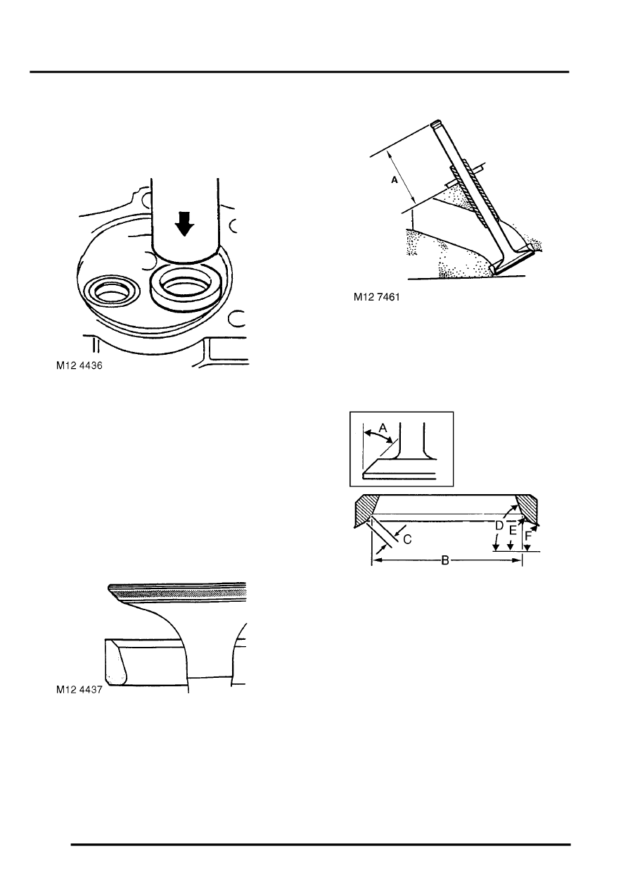
28. Using a suitable mandrel, press new insert fully
into counterbore.
29. Allow cylinder head to air cool.
CAUTION: Renew worn valve guides and/or
valve seats before lapping the valves.
30. Recut valve seat in head and lap in valves
using fine paste.
31. Coat valve with a small quantity of engineer's
blue, insert valve and press into position
several times without rotating. Seating position
should be in centre of valve face.
32. Check valve installed height if valve seats have
been refaced or renewed.
l
Valve installed height, end of valve to base
of spring seat, 'A' = 44.16 to 45.29 mm (1.74
to 1.80 in).
33. Reface valves as necessary. If a valve has to
be ground to a knife-edge to obtain a true seat,
renew valve.
34. Cut valve seats using suitable cutters:
l
Valve seat angle 'A' = 45
°
.
l
Valve seat insert diameter 'B' Inlet = 36.83
mm (1.45 in).
l
Valve seat insert diameter 'B' Exhaust =
31.50 mm (1.24 in).
l
Seating width 'C' - Inlet = 0.89 to 1.4 mm
(0.035 to 0.055 in).
l
Seating width 'C' - Exhaust = 1.32 to 1.83
mm (0.052 to 0.072 in).
l
Angle 'D' = 70
°
.
l
Angle 'E' = 46
°
to 46
°
25'.
l
Angle 'F' = 20
°
.
Parts & tools for this job For Land Rover Discovery
- PARTEngine gasket setSearch: Land Rover Discovery engine gasket set
- TOOLTorque wrenchSearch: 3/8 inch torque wrench
- TOOLFeeler gauge setSearch: feeler gauge set
Links open Amazon search results in a new tab. As an Amazon Associate I earn from qualifying purchases.