
Freelander System Description and Operation
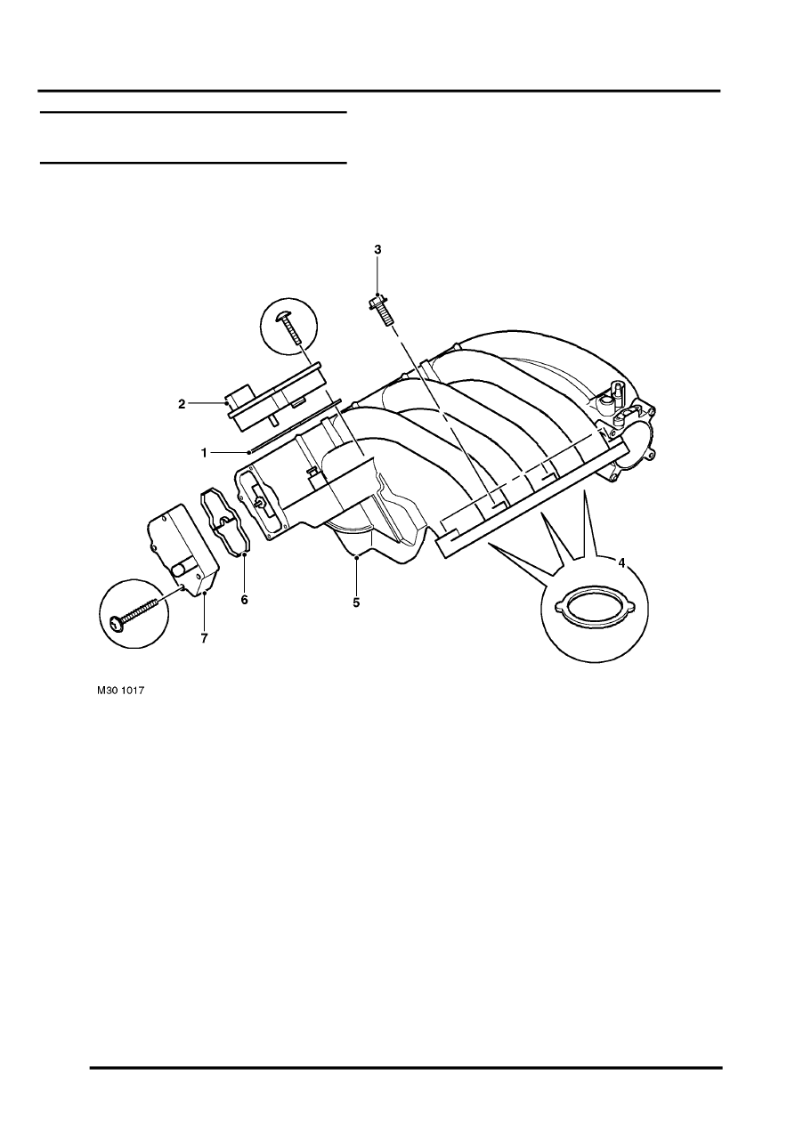
MANIFOLD AND EXHAUST SYSTEM - K SERIES KV6
30-3-2
DESCRIPTION AND OPERATION
Inlet Manifold Chamber Component
Layout
1 Seal
2 Power valve motor – Variable Intake System
(VIS)
3 Flanged bolt (4 off)
4 Seal (3 off)
5 Inlet Manifold Chamber
6 Seal
7 Balance valve motor – (VIS)