
Freelander Service Procedures
ENGINE - K SERIES KV6
OVERHAUL 12-3-99
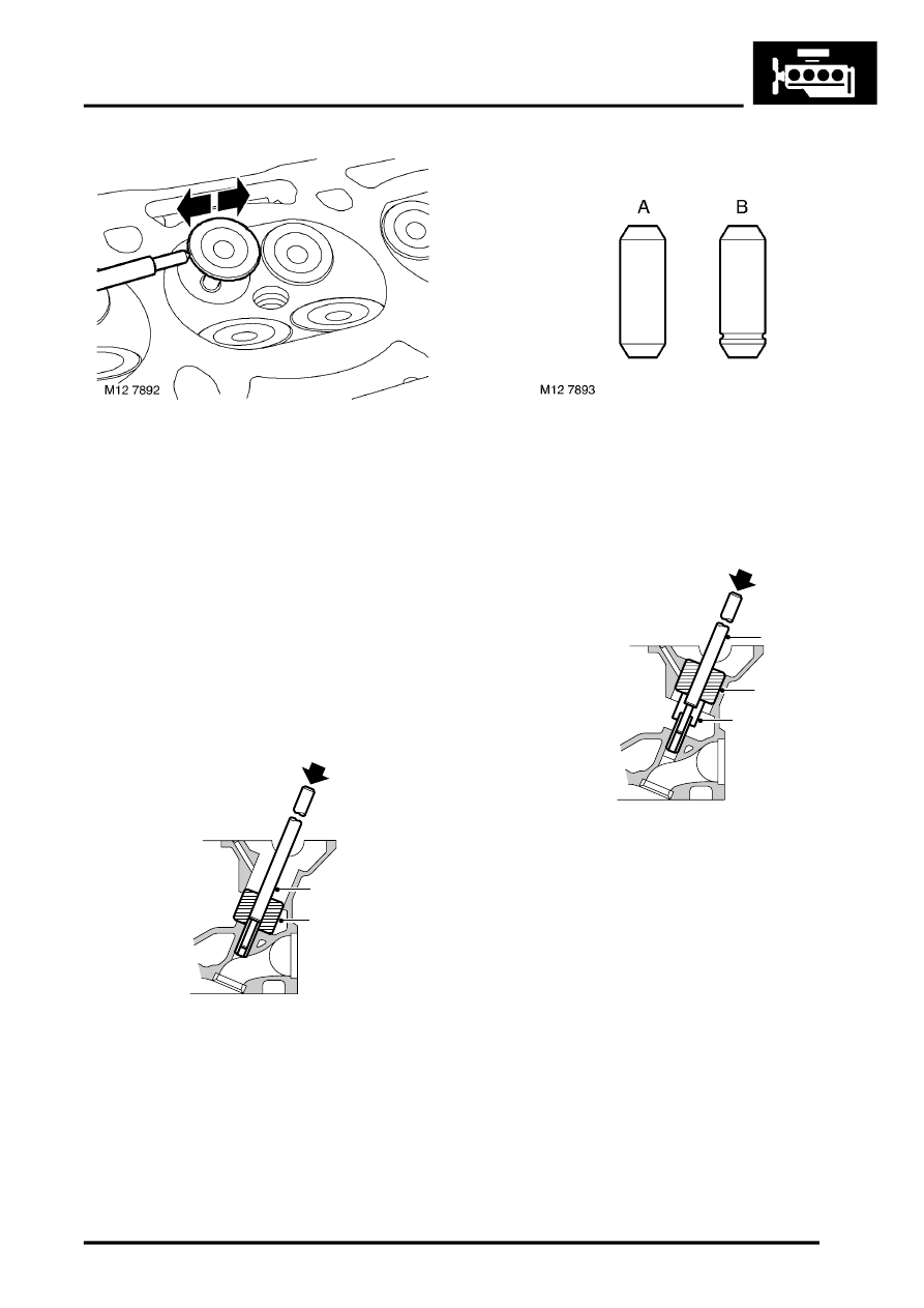
20. Insert each valve into its respective guide.
21. Extend valve head 15 mm (0.6 in) out of guide
and position DTI gauge to rear of valve head.
22. Move valve towards front of cylinder head and
zero gauge ensuring that stylus of gauge
remains in contact with valve head.
23. Move valve towards rear of cylinder head,
record gauge reading obtained to give valve
stem to guide clearance 'B'.
24. Remove valves ensuring they are retained in
their fitted order.
25. Renew valves and/or guides as necessary.
26. To replace valve guides support cylinder head
face down on wooden blocks.
27. Position LRT-12-519-3 in tappet bore and drift
out valve guide using LRT-12-519-1.
CAUTION: Retain guides in their fitted
order.
28. Identify type of valve guide fitted: 'A' - Standard
production 'B' - Service replacement.
CAUTION: Standard production valve
guides A must be replaced with service
replacement guides B.
29. Locate valve guide in valve guide bore with
identification groove towards valve seat and
position depth gauge LRT-12-519-2 onto valve
guide.
CAUTION: Cylinder head and valve guides
must be at room temperature when fitting
guides.
30. Position nylon guide LRT-12-519-3 in cylinder
head, press guide into bore using driver LRT-
12-519-1 until depth gauge contacts cylinder
head.
M12 6890
LRT-12-519-1
LRT-12-519-3
M12 6892
LRT-12-519-2
LRT-12-519-1
LRT-12-519-3