
Component location table
- Make
- Land Rover
- Model
- Range Rover P38 Electrical Troubleshooting Manual
- Year
- 1995
- Section
- Circuit diagram › Component location table
COMPONENT LOCATION TABLE
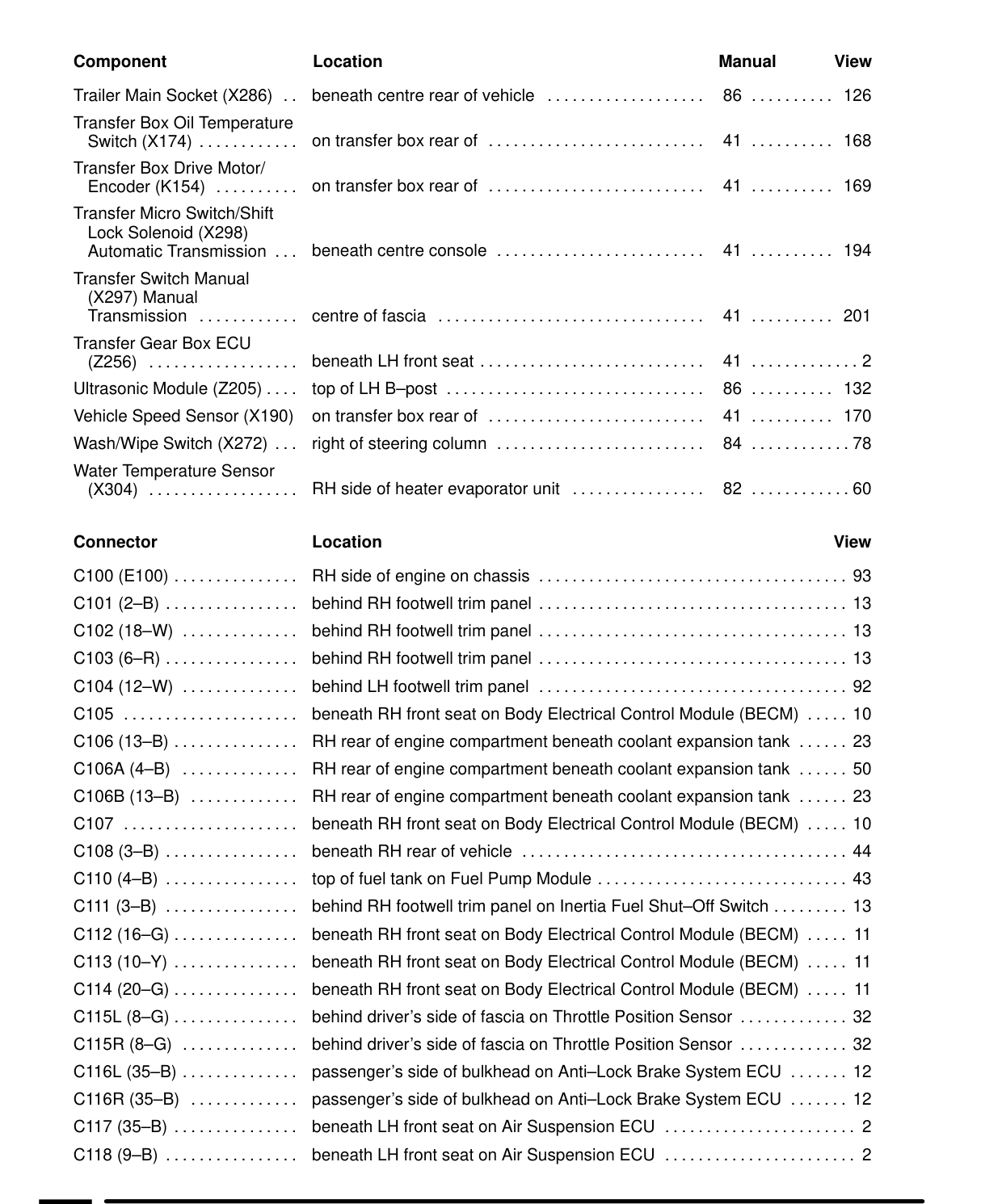
24 COMPONENT LOCATION TABLE
Component Location
Trailer Main Socket (X286) beneath centre rear Transfer Box Oil Temperature Switch (X174) ............ ontransferboxrearof
Transfer Box Drive Motor/ Encoder (K154) ontransferboxrearof
Transfer Micro Switch/Shift Lock Solenoid (X298) Automatic Transmission ... beneath centreconsole ......................... Transfer Switch Manual (X297) Manual Transmission centreoffascia
Transfer Gear Box ECU (2256) beneathlLHfrontseat........................... Module (2205) .... topof LHB—post .................. ccc. Ultrasonic Vehicle Speed Sensor (X190) on transferboxrearof Switch (X272) ... right of steeringcolumn ......................... Wash/Wipe Water Temperature Sensor (X804) .................. RH side of heater evaporatorunit
Connector Location
C100 (E100) ............... RHsideofengineonchassis ..................ciiiviinnann.... 93 C101 (2-B) ................ behind RH footwell trimpanel ..................................... C102 (18-W) .............. behind RH footwell trimpanel ..................................... C103(6-R)................ behind RH footwell trimpanel ..................................... C104 (12-W) behind LH footwell trimpanel ...........................o....
C105 ..................... beneath RH front seat on Body Electrical Control Module (BECM) ..... 10 of engine compartment beneath coolant expansion tank ...... C106 (13-B) ............... RH rear of engine compartment beneath coolant expansion tank ...... 50 C106A(4-B) RH rear of engine compartment beneath coolant expansion tank ...... C106B (13-B) RH rear C107 ..................... beneath RH front seat on Body Electrical Control Module (BECM) ..... 10
C108 (3B) ................ beneathRHrearofvehicle ................. C110(4-B) ................ topoffueltank on Fuel PumpModule .............................. C111 (3-B) ................ behind RH footwell trim panel on Inertia Fuel Shut-Off C112 (16-G) ............... beneath RH front seat on Body Electrical Control Module (BECM) .....
C113 (10-Y) ............... beneath RH front seat on Body Electrical Control Module (BECM) .....
C114 (20-G) ............... beneath RH front seat on Body Electrical Control Module (BECM) .....
C115L (8-G)............... behind driver’s side of fascia
C115R (8-G) behind driver’s side of fascia side of bulkhead on Anti-Lock Brake System ECU ....... 12 C116L (35-B) .............. passenger's side of bulkhead on Anti-Lock Brake System ECU ....... 12 C116R (35-B) passenger's C117 (35-B) ............... beneath LH front seat on Air SuspensionECU
C118 (9-B) ................ beneath LH front seat on Air SuspensionECU
Manual View
of vehicle 86 .......... 126
41 168
41 169
41 194
41 oo... .... 201
41 86 LoL... 132 41 170 84 ............78
82 ............60
View
13 13 13 92
23
23
ccc. iii. ...... 44 43 Switch ......... 13 11
11
11
on Throttle Position Sensor ............. 32 on Throttle Position Sensor ............. 32
Parts & tools for this job For 1995 Land Rover Range Rover
- TOOLDigital multimeterSearch: automotive digital multimeter
- PARTAssorted fuse kitSearch: car fuse assortment kit
- TOOLWire crimper and connector kitSearch: wire crimper connector kit
Links open Amazon search results in a new tab. As an Amazon Associate I earn from qualifying purchases.