
Step 4
- Make
- Mazda
- Model
- MX-5 (NA) Factory Workshop Manual
- Year
- 1990–1992
- Section
- [T] › Step 4
Body electrical systemStep 4
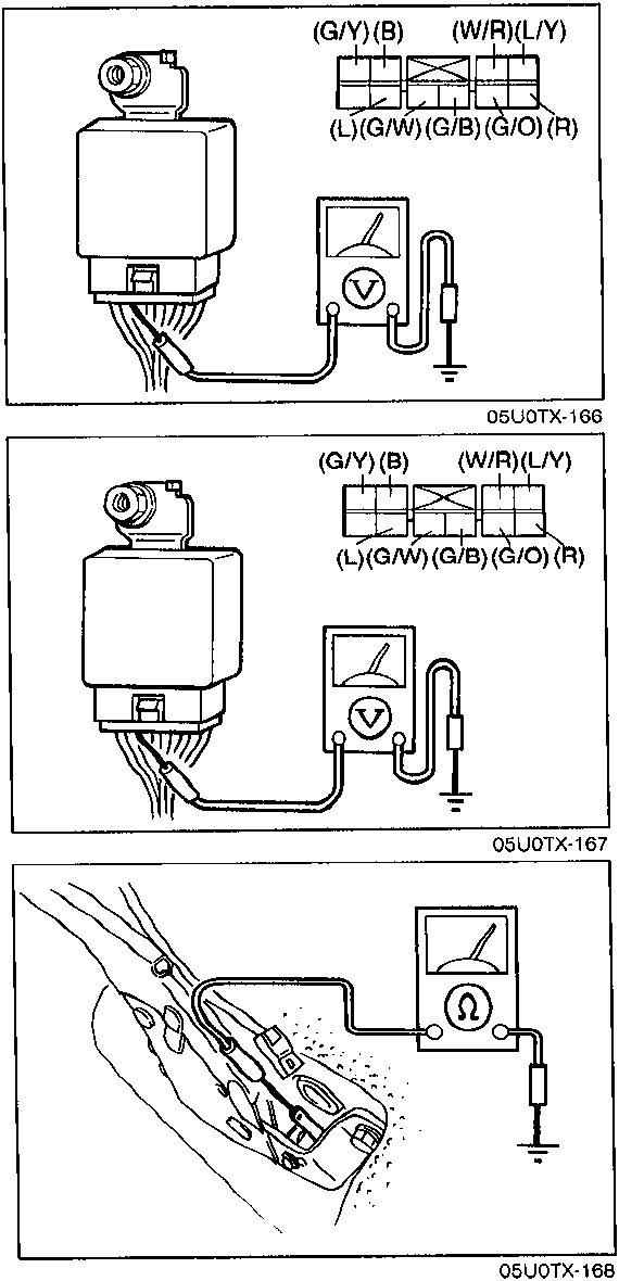
Step 4
- Turn on the ignition switch.
- Turn on the headlight switch.
- Check the voltage at the following terminal-wires of the DRL unit connector.
| Wire | Voltage |
|---|---|
| (G/B) | Cycles 12V and 0V |
| (G/W) | Cycles 12V and 0V |
- If not as specified, repair the wire harness. (Turn and hazard warning flasher unit — DRL unit)
- If correct, replace the DRL unit.
Step 5
- Turn on the ignition switch.
- Pull the parking brake lever more than one notch.
- Check the voltage at terminal-wire (R) of the DRL unit connector.
| Wire | Voltage |
|---|---|
| (R) | 0V |
- If not as specified, go to Step 6.
- If correct, replace the DRL unit.
Step 6
- Disconnect the parking brake switch connector.
- Check continuity between the terminal of the switch and a body ground.
| Parking brake lever | Continuity |
|---|---|
| Pulled one notch | Yes |
| Released | No |
- If not as specified, adjust or replace the parking brake switch.
- If correct, repair wires (R) and (L/Y). (Parking brake switch — DRL unit)
Removal / Installation
Refer to the following pages:
| Item | Reference page |
|---|---|
| Headlight switch (in combination switch) | T–23 |
| Hazard warning switch | T–25 |
| Turn signal switch (in combination switch) | T–23 |
| Daytime running lights (Front turn signal lights) | T–69 |
Parts & tools for this job For 1990 Mazda MX-5
- TOOLDigital multimeterSearch: automotive digital multimeter
- PARTAssorted fuse kitSearch: car fuse assortment kit
- TOOLWire crimper and connector kitSearch: wire crimper connector kit
Links open Amazon search results in a new tab. As an Amazon Associate I earn from qualifying purchases.