
Engine management system - MEMS (Fuel system): Description and operation
- Make
- Mini
- Model
- Mini Workshop Manual
- Year
- 1996–2000
- Section
- Description and operation › Fuel system
Engine management system - MEMSFuel system
FUEL SYSTEM
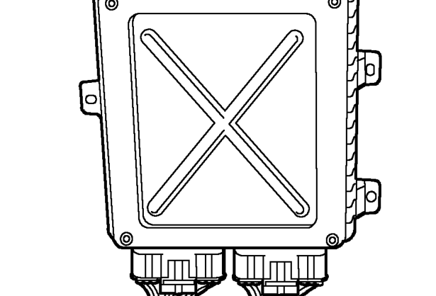
Engine Control Module (ECM)
| INPUTS Crankshaft position sensor Camshaft position sensor Manifold absolute pressure sensor Engine coolant temperature sensor Intake air temperature sensor Heated oxygen sensor Throttle position sensor Diagnostic input Battery supply Starter signal Earth supply Anti-theft control unit |
| ECM |
The Modular Engine Management System (MEMS) is controlled by an ECM mounted in the engine compartment. The ECM is an adaptive unit which over a period of time learns the load and wear characteristics of the engine it controls. The ECM remembers and updates two main engine requirements when the engine is running at normal operating temperature:
- The position of the idle air control (IAC) valve required to achieve a specified idle speed. This is then used as a reference for IAC valve movement to achieve idle speed under all load conditions.
- The fuelling change or offset required to achieve a set oxygen sensor voltage. This allows the system to provide the correct fuelling without having to apply excessive adjustments to the fuelling which can adversely affect the emissions and driveability.
NOTE: After fitting a different ECM, TestBook will be required to reprogramme the ECM with the code from the anti-theft control unit and to perform a full engine tune procedure.
The ECM inputs and outputs are shown in the following table:
| OUTPUTS Purge valve Ignition coil Injectors Idle air control valve Fuel pump relay Diagnostic connector Heated oxygen sensor relay Main relay Cooling fans Air conditioning |
Parts & tools for this job For 1996 Mini Mini
- PARTFuel filterSearch: Mini Mini 1996 fuel filter
- TOOLFuel pressure test kitSearch: fuel pressure test kit
- TOOLFuel line disconnect toolSearch: fuel line disconnect tool
Links open Amazon search results in a new tab. As an Amazon Associate I earn from qualifying purchases.