
Idle air control valve
- Make
- Mini
- Model
- Mini Workshop Manual
- Year
- 1996–2000
- Section
- Description and operation › Idle air control valve
Idle air control valve
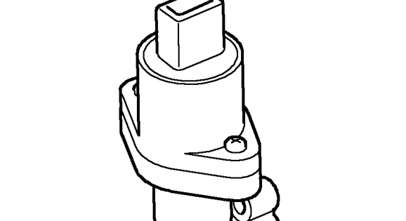
The idle air control valve (IACV) is mounted on the inlet manifold and controlled by the ECM. The IACV opens a pintle valve situated in an air passage in the throttle housing, allowing air to bypass the throttle disc and flow straight into the inlet manifold.
By changing the amount the IACV is open the ECM can control engine idle speed and cold start air flow requirements by adjusting the flow of air in the passage.
During cold starting the ECM indexes the IACV open slightly to provide a level of fast idle, dependent on engine coolant temperature. As the engine warms, fast idle is gradually decreased until normal operating temperature is reached.
The position of the IACV should be within the range of 20 to 40 steps when the engine is running.
NOTE: Adjustment of the IACV only applies to the ’learnt’ position, not the actual position at idle, so adjustment is not recommended.
If the valve is identified as being outside this range it can be adjusted to within range using TestBook. This ensures that the IACV is at the optimum position within its range for providing further movement to compensate for changes in engine load or temperature in accordance with signals from the ECM.
NOTE: The position of the throttle disc is preset during manufacture and the throttle position setting screw MUST NOT be adjusted.
Relay module
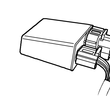
The relay module is located in the engine compartment adjacent to the engine control module. The relay module contains the following relays:
- Main relay - energised when the ignition is switched on and supplies power to the ECM.
- Fuel pump relay - energised by the ECM for a short period when the ignition is switched on, during cranking and while the engine is running.
- Starter relay - energised by the cranking signal from the ignition switch.
- Heated oxygen sensor (HO2S) relay - energised by the ECM and supplies current to the heated oxygen sensor element.
Purge valve
The purge valve is driven directly from by the ECM. When the purge valve is opened it allows the EVAP canister to vent into the engine inlet manifold. The valve is opened by the ECM for varying periods under specific engine conditions to avoid degrading engine performance.
Parts & tools for this job For 1996 Mini Mini
- PARTEngine gasket setSearch: Mini Mini 1996 engine gasket set
- TOOLTorque wrenchSearch: 3/8 inch torque wrench
- TOOLFeeler gauge setSearch: feeler gauge set
Links open Amazon search results in a new tab. As an Amazon Associate I earn from qualifying purchases.