
Engine management system - MEMS (Throttle housing): Description and operation
- Make
- Mini
- Model
- Mini Workshop Manual
- Year
- 1996–2000
- Section
- Description and operation › Throttle housing
Throttle housing
The throttle housing is located between the inlet manifold and air intake hose and is sealed to the manifold by an ’O’ ring. The throttle housing incorporates a throttle disc which is connected to the throttle pedal via the throttle lever and a cable.
There are two breather pipes connected to the throttle housing; one either side of the throttle disc. When the engine is running with the throttle disc open, both pipes are subject to manifold depression and draw crankcase fumes into the manifold. When the throttle disc is closed, only the pipe on the inlet manifold side of the disc is subject to manifold depression. This pipe incorporates a restrictor to prevent engine oil being drawn into the engine by the substantially greater manifold depression.
Mounted on the throttle housing are the throttle position sensor and idle air control valve.
Throttle position sensor
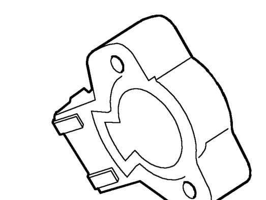
The throttle position (TP) sensor is a potentiometer attached to the throttle housing and is directly coupled to the throttle disc. The TP sensor is non-adjustable. Closed throttle is detected by the TP sensor which initiates idle speed control via the idle air control valve.
The ECM supplies the TP sensor with a 5 volt supply and an earth path. The TP sensor returns a signal proportional to throttle disc position.
Throttle disc movement causes voltage across the TP sensor to vary. The ECM calculates the rate of change of the voltage signal in positive (acceleration) or negative (deceleration) directions. From this the ECM can determine the required engine speed, rate of acceleration or rate of deceleration and apply acceleration enrichment, deceleration fuel metering or over-run fuel cut-off.
Parts & tools for this job For 1996 Mini Mini
- PARTEngine gasket setSearch: Mini Mini 1996 engine gasket set
- TOOLTorque wrenchSearch: 3/8 inch torque wrench
- TOOLFeeler gauge setSearch: feeler gauge set
Links open Amazon search results in a new tab. As an Amazon Associate I earn from qualifying purchases.