
Drive shaft and outer joint - ’d’ series (page 2 of 2)
- Make
- Rover
- Model
- 400 Workshop Manual
- Year
- 1995–2000
- Section
- Repairs
Drive shaftsDrive shaft and outer joint - ’d’ series · page 2 of 2
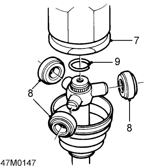
- Remove inner joint from shaft.
- Remove bearings from spider.
- Remove circlip retaining spider to shaft.
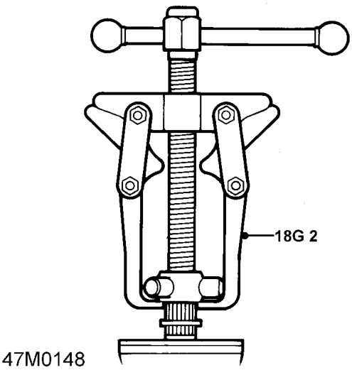
- Using tool 18G 2 remove spider from shaft.
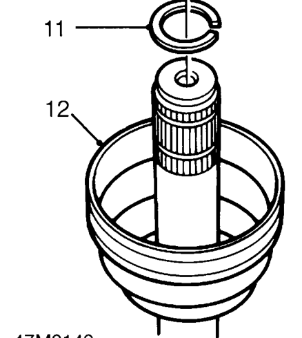
- Remove stopper ring from shaft.
- Remove gaiter from shaft and inspect for damage and renew if necessary.
- Fit new drive shaft to vice.
- Clean shaft and joint components.
Refit
- Fit gaiter to shaft.
- Fit stopper ring to shaft, fit spider to shaft and secure with circlip.
- Fit bearings to spider with shoulders facing outwards.
- Apply 100g to 118g of grease from the sachet to outer joint and bearings.
- Fit joint onto shaft.
- Position gaiter to joint and use a Band-it thriftool to secure the 2 new clips.
- Fit drive shaft. See this section.
Parts & tools for this job For 1995 Rover 400
- PARTWheel bearingSearch: Rover 400 1995 wheel bearing
- TOOLBearing puller kitSearch: wheel bearing puller kit
- PARTCV boot kitSearch: Rover 400 1995 cv boot kit
Links open Amazon search results in a new tab. As an Amazon Associate I earn from qualifying purchases.