
Airbag manual deployment
- Make
- Rover
- Model
- 400 Workshop Manual
- Year
- 1995–2000
- Section
- Precautions › Airbag manual deployment
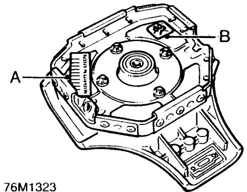
- Airbag module
A- ROVER Part Number - The code number must be quoted when ordering a replacement module. - ROVER Bar code - The code number must be recorded if the airbag module is to be replaced.
WARNING: Refer to Workshop Manual.
B- Supplementary restraint system (airbag).
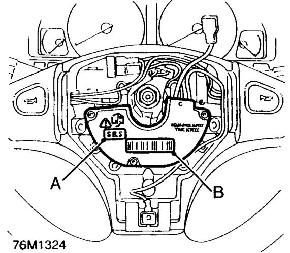
- Control and diagnostic unit.
A- Refer to the Workshop Manual for information on the airbag system.
B- ROVER Bar Code - The code number must be recorded if the airbag control and diagnostic unit is to be replaced.
AIRBAG MANUAL DEPLOYMENT
If a vehicle is to be scrapped and contains an undeployed airbag module, or pre-tensioner - from 1997.5 MY, the components must be manually deployed. This operation should only be carried out using the following recommended manual deployment procedure.
Before deployment is started the deployment tool self test procedure should be carried out.
Deployment tool SMD 4082/1 self test procedure
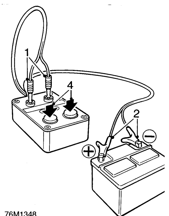
- Insert BLUE and YELLOW connectors of tool lead into corresponding sockets on face of tool.
- Connect crocodile clips of second tool lead to battery, RED to positive and BLACK to negative.
- Red "READY" light should illuminate.
- Press and hold both operating buttons.
- GREEN "DEFECTIVE" light should illuminate.
- Release both operating buttons.
- RED "READY" light should illuminate.
- Disconnect tool from battery.
- Disconnect BLUE and YELLOW connectors from tool face sockets.
- Self test now complete.
Parts & tools for this job For 1995 Rover 400
- TOOLOBD2 scanner with SRSSearch: OBD2 scanner ABS SRS
- TOOLTrim removal tool kitSearch: trim removal tool kit
Links open Amazon search results in a new tab. As an Amazon Associate I earn from qualifying purchases.