
Modulator pump
- Make
- Rover
- Model
- 600 Rover 600 Repair Manual - Volumes 1 and 2 - 2nd Edition
- Section
- Repairs › Modulator pump
Brakes – ABS BY4Modulator pump
- Install the modulator unit in the reverse order of removal.
Note: Insure each outlet pipe is fitted to the correct port identified by code letters, tighten to 19 Nm.
- After installation: Fill the brake master cylinder reservoir.
- Start engine and idle for one minute.
Check that:
ABS warning light is OFF.
Brake fluid is not leaking from pipe unions. - Stop engine and check fluid level in reservoir, top – up to MAX level.
- Bleed the brake system.
- Check ABS function using TestBook.
MODULATOR PUMP
Removal/Installation
WARNING: Before removing the modulator, be sure to relieve the high pressure fluid from the bleed screw.
- Remove the modulator assembly,
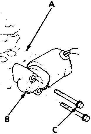
15 Nm
- Modulator unit
- Pump motor
- Flange bolt
- 'O' ring
- Remove 2 flange bolts securing pump motor to modulator.
- Remove pump motor from modulator.
- Remove and discard 'O' ring seal.
- Install the pump motor in the reverse order of removal, use a NEW 'O' ring seal.
Note: After installing the modulator, bleed air from the system,
Check ABS warning light operation
Parts & tools for this job For Rover 600
- TOOLOBD2 scanner with ABSSearch: OBD2 scanner ABS SRS
- TOOLDigital multimeterSearch: automotive digital multimeter
Links open Amazon search results in a new tab. As an Amazon Associate I earn from qualifying purchases.